-
-
November 29, 2024 at 10:05 am
SR786
SubscriberHi,
I am simulating batch mixing in a stirred tank, injecting a small volume of tracer into a tank filled with water and tracking the concentration profile at several locations to get the mixing time. For this simulation, I am assuming the tracer doesn't influence the flow field (same properties of bulk fluid) so I only need to solve one equation for the transport of tracer. I have followed the general steps in terms of setting up the simulation which include:
- Solving steady state flow field using SST K-Omega with curvature correction.
- Activate species transport and create mixture template for water-tracer. Tracer physical properties will be the same as water. Change diffusivity of tracer in water from default value (2.88e-05) to literature value 1.47e-09.
- Switch off flow and turbulence equations, leaving only one equation for transport of tracer.
- Patch small volume of tracer into computational domain near the top of the liquid (injection point was very close to the wall, 0.2 cm away).
- Set up concentration probes at several locations in the tank.
- Run simulation.
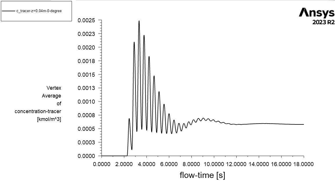
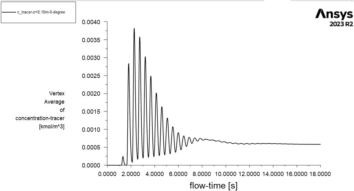
When I run the simulation, I notice the mixing behaviour in the tank appears to be physically unrealistic where there are heavy fluctuations observed at all the monitoring locations (there should only be some fluctuations near the point of injection). Here are two plots, one near the bottom of the tank (0.04 m) and one near the point of injection (0.10 m). Both monitors give severe fluctations
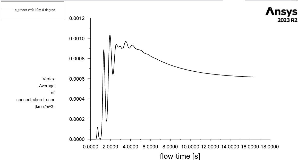
I am unsure as to what is causing this issue. For comparison I ran another simulation using the steady state profile from standard k-epsilon as opposed to SST k-omega with curvature correction and found a more reasonable profile behaviour (see profiles below). What possible reasons could there be for the degradation of SST K-Omega with curvature correction predictions and how can I resolve this to get a more physically realistic profile?
-
November 29, 2024 at 11:08 am
Rob
Forum ModeratorHow large a volume did you patch? Those concentration plots are showing a near zero volume fraction, and I'd also use an isosurface to see what's going on: relying on a few points monitors isn't recommended.
-
November 29, 2024 at 11:44 am
SR786
SubscriberHi,
Thank you for your reply, I patched a small amount of tracer (24 cells) into a ~1.5 million cell domain. For the experiment a small volume (2 mL) of tracer was injected into a volume of water. The tank volume is 5.3 L and is half filled with water (2.65 L) which is what I am simulating in this run (upto the liquid height, flat surface). Do I need to patch more cells into the computational domain?
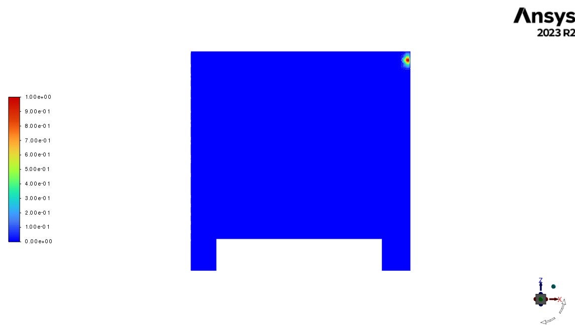
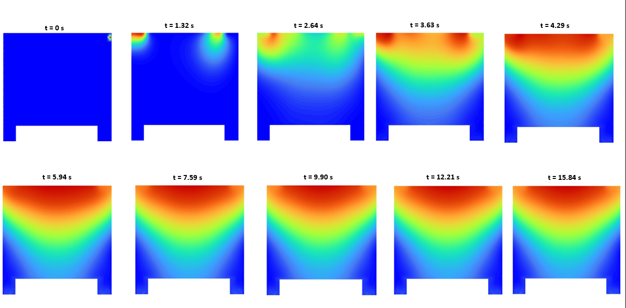
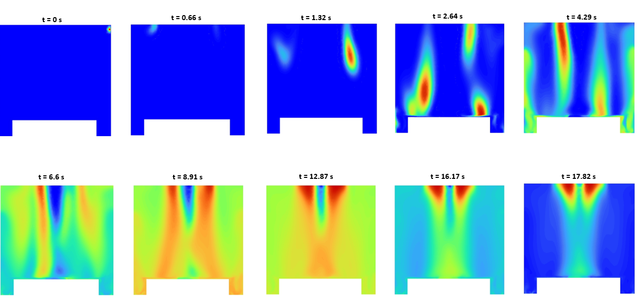
Also these are the mass fraction contours for standard k-epsilon & SST k-omega with curvature correction. As the tank is unbaffled, there should be strongly swirling flow with tangential velocity dominating. The dispersion predicted by the SST k-omega with curvature correction doesn't look realistic.
Standard K-Epsilon
SST K-Omega With Curvature Correction:
-
November 29, 2024 at 11:52 am
Rob
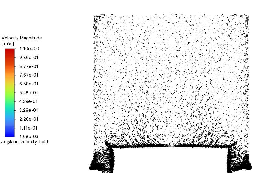
Forum ModeratorHow does the flow field look? You'll find axial, tangential & radial velocity options in contours. With very strong swirl both fixed lid approximation and two equation turbulence models may not be suitable.
-
November 29, 2024 at 12:06 pm
SR786
SubscriberHi
A jet produced from tip of stirrer hitting wall, flow is then directed upwards towards the top surface of the tank before returning to the stirrer forming a recirculating pattern.
I am modelling a flat-liquid surface to check if my methodology is correct before adding the tracer to a VOF simulation with vortex.
Also regarding setting the tracer properties the same as water, do I also need to define the molecular weight of tracer as the same as water or do I use the actual molecular weight of tracer as I took it as the molecular weight of tracer used in the experiment?
-
November 29, 2024 at 12:15 pm
Rob
Forum ModeratorMolecular weight may matter if you're using that to calculate anything, but in a mixing tank I'm not sure it's needed unless you're reacting something.
So, classic mixing tank flow. I'd expect k-e to give a good enough result. But as I can't see any flow images it's hard to judge.
-
November 29, 2024 at 12:23 pm
-
November 29, 2024 at 1:29 pm
Rob
Forum ModeratorMore critically, look at how the flow passes from the scalar release into the bulk flow - you aren't always looking for big differences in flow to have a very different number value result.
-
- You must be logged in to reply to this topic.


-
4838
-
1587
-
1386
-
1242
-
1021

© 2026 Copyright ANSYS, Inc. All rights reserved.

