-
-
October 28, 2019 at 8:18 pm
-
October 28, 2019 at 8:39 pm
Mark Christini
Ansys EmployeeCurrent (or voltage) values entered in the Eddy Current solver are peak values of a sinusoidal signal centered around zero.
You can create a named expression in the calculator for: integral J at phase on a terminal and plot vs phase angle to see the sinusoidal waveform.
-
May 19, 2020 at 5:25 pm
sneha13thakur
SubscriberHi
Â
I am using the eddy current simulator for two winding planar transformer simulation. please help in answering my few questions:
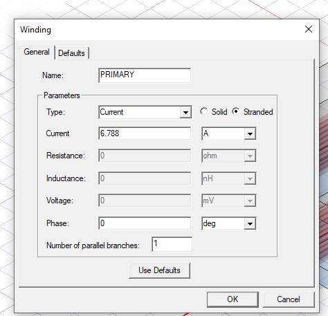
1. While giving the coil excitation as current should I give the peak value "Ipk" or write the trapezoidal current equation?
2. If I have two pcbs dedicated to one winding (two pcbs connected in parallel). Should I mention no of parallel branches as 2 or 1? Should i give the current excitation as "Ipk" or "Ipk/2"?
2. After giving a peak value as excitation, the flux density is too high which leads to high core losses. How can I reduce the flux density?
Â
Thank you
-
October 5, 2023 at 12:31 pm
irem taÅŸ
Subscriberwhen I try to do skin depth the top and and bottom of my cylinder have gone. I guess that's why my core loss seems 0. How can I fix that please help me? and Is skin depth analyse necessary for eddy current analyse?
-
- The topic ‘Ansys Maxwell Eddy Current Simulator’ is closed to new replies.
-
6625
-
1906
-
1469
-
1311
-
1022
© 2026 Copyright ANSYS, Inc. All rights reserved.
