-
-
September 6, 2024 at 11:05 pm
aagalvez
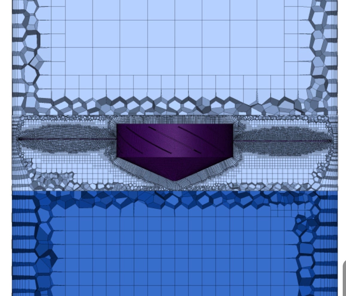
SubscriberHello, everyone. I have a concern regarding meshing. I want to replicate the baseline case (shown in the first picture-in color blue), basically there are 3 domains (stator outlet, inlet and the rotor domain). My mesh figure(shown in second picture-in color violet) dont really match with that of the baseline case, specifically in the rotor zone. How can I make that type of meshing especially on the baseline case's propeller meshing? I already tried local sizing (proximity and curvature) amd also set some buffer layers and peel layers... thank you in advance for your help.
BASELINE CASE
MY MESHING
-
September 9, 2024 at 12:28 pm
Federico
Ansys EmployeeHello,
what specific part do you feel like you are not getting? Other than the missing inflation layers in mesh 2, I would argue that it looks slightly better from those screenshots.
Mesh 1 appears to have a larger Max. Cell size in the Volume Mesh task. It seems to me that Peel layer is 1 and Buffer layers is 2 in Mesh 1.
-
September 25, 2024 at 12:50 pm
aagalvez
SubscriberThank you Federico for your comment. This one was already resolve
-
- You must be logged in to reply to this topic.


-
4909
-
1603
-
1386
-
1242
-
1021

© 2026 Copyright ANSYS, Inc. All rights reserved.


