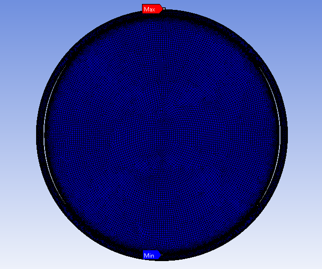
Can I create bonded/rough contact between two surface with slight gap in between
-
-
September 4, 2024 at 10:59 am
Sushant
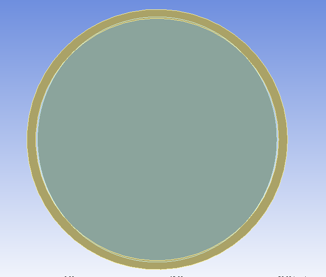
SubscriberHello, I am working on a 2D static structural in ansys workbench, I solving for a assembly of circular ring and solid elliptical cam, refer to the attached image. I am using 2 steps for this, in 1st step = using frictionless contact with interface treatment of " Add offset, ramped effect." to tackle the intial interface and expecting that circular ring will take shape of elliptical cam. In step 2 = using bonded contact, cause I want, there should not be any relative motion between two parts after assembly
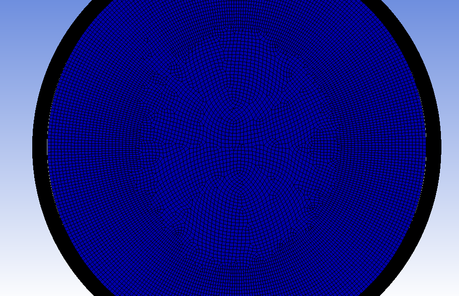
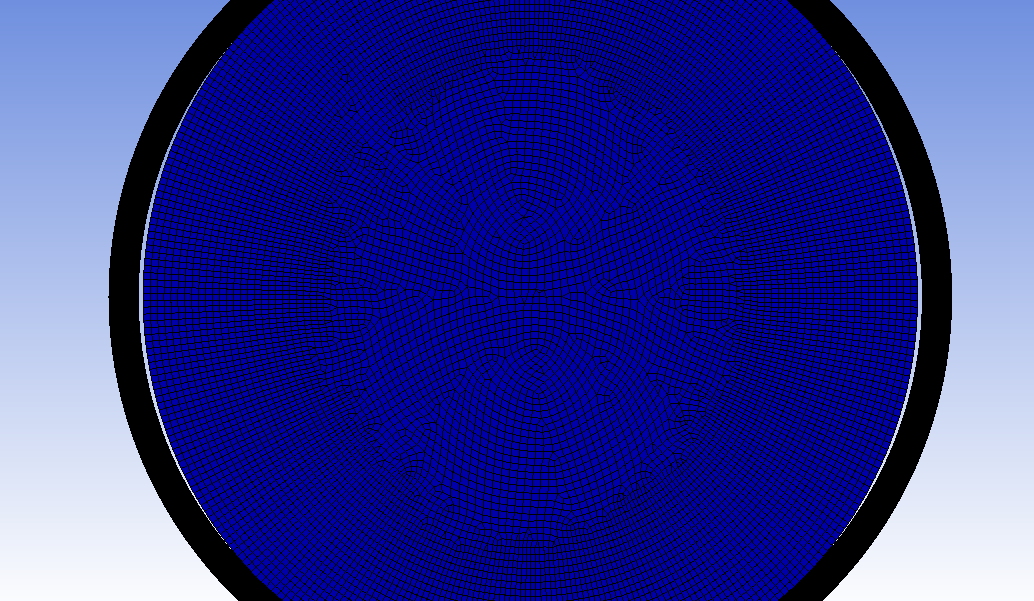
Problem facing : I succesfuly completed step 1 but after step1 completion there is slight gap between two edges approx 40-50 microns and due to that in step 2 I am not able to create bonded contact, solver showing convergence error and end up on inital stage. So can I create bonded/rough contact between edges with slight gap in between
Step 1 Step 2 Frictionless Alive Dead Bonded Dead Alive Please suggest required contact settings.
Images attached : 1) Inital Geometry 2) Deformation after step1 3) Deformation after step2.
-
September 4, 2024 at 11:51 am
Nanda
Ansys EmployeeHello Sushant,
Can you try exploring some contact settings? We recommend using the "Adjust to touch" setting under the geometric modification feature.
Adjust to touch: Any initial gaps are closed and any initial penetration is ignored creating an initial stress-free state. Contact pairs are "just touching". This setting is useful to ensure initial contact occurs even if any gaps are present (as long as they are within the pinball region). Without this setting, the bodies may fly apart if any initial gaps exist or might lead to convergence issues similar to what you're experiencing.
9.6.3.5. Geometric Modification (ansys.com)Please let us know if this didn't help.
Regards,Nanda.
If you are not able to open Ansys help links, refer to this forum discussion: How to access the ANSYS Online Help
Also, we launched a public help documentation website: Ansys Help
For more exciting courses and certifications, hit this link: Ansys Innovation Courses | Ansys Innovation Space
-
September 4, 2024 at 2:11 pm
Sushant
SubscriberHello Nanda,
Thank you for prompt reply. As you mentioned, in step1 I used 'Adjust to touch' with frictionless condition, but it didn't work. Ring didn't diform at all in step1 itself, refer attached image. There is non-uniform gap between two bodies. If you see the inital geometry there is gap along minor axis (Horizontal) and penetration along Major axis (vertical).
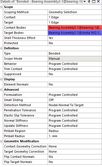
Step1 with frictionless and 'Add offset, Ramped effects' is working very well. Can you suggest me different setting for step2 i.e. Bonded. in bonded we don't have any option for interface treatment and initial contact status for both is showing 'closed'. so the value of pinball radius is sufficient.
Is switching from frictionless to bonded making things difficult.
-
September 4, 2024 at 2:42 pm
Nanda
Ansys EmployeeHello Sushant,
Given that the “Adjust to touch” setting did not work in your case, and considering the already good enough mesh quality you have, here are a few suggestions for step 2:Penetration Tolerance Adjustment: Increase the penetration tolerance in the bonded contact settings. This might help in accommodating the slight gaps or penetrations that are causing the convergence issues. You can manually set the penetration tolerance to a value slightly higher than your gap (40-50 microns). 9.6.3.3. Advanced Settings (ansys.com)
Pinball Region: Ensure that the pinball region radius is adequately large to cover the gaps. (link 9.6.3.3 has details of pinball too)
Switch Contact Formulation: If the current contact formulation is “Program Controlled”, try switching it to “Augmented Lagrange” or “Pure Penalty”. These formulations can sometimes handle initial gaps better by allowing some penetration without causing convergence issues. 9.6.2. Contact Formulation Theory (ansys.com)
Alternative Contact Type: Use this as a last resort, If bonded contact continues to cause issues, consider using a “No Separation” contact instead of bonded. This will allow the surfaces to come into contact without relative motion but might handle initial gaps better. 9.6.5. Setting Contact Conditions Manually (ansys.com)
Try implementing these suggestions and see if they resolve the convergence issues. You might need to experiment with a combination of these settings to find the best solution for your specific case. Please, let us know if the above suggestions didn’t work out.
Best,
Nanda -
September 6, 2024 at 9:37 am
Sushant
SubscriberThanks Nanda, setting 'Penetration Tolerance Adjustment' to 0.1mm solved my problem and I am able to simulate Bonded contact succefully.
-
September 6, 2024 at 11:58 am
Nanda
Ansys EmployeeThanks for letting us know. Happy Simulation!
-
- You must be logged in to reply to this topic.


-
5039
-
1749
-
1387
-
1248
-
1021

© 2026 Copyright ANSYS, Inc. All rights reserved.

