-
-
April 5, 2024 at 4:35 pm
kyungha.lee
SubscriberHello, everyone.
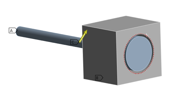
I am modelling and running a simple simulation, where a beam element is placed in a cube with a hole slightly bigger diameter than the beam element as shown below. What I want to see is the movement of the beam when a lateral accelearation is applied to the model, while the other end of the beam and the bottom side of the cubic element is fixed. However, I have found that the beam is penetrating the cubic element, which is not realistic. I tried firctionless contact by setting adjust to touch, however this prevents the lateral movment of the end part of the beam as well, which is again unrealistic.
Could anyone give me a solution on contract definition to allow beam to move upto the boundary of the cubic element but does not penetrate? -
April 8, 2024 at 8:07 am
Stella Peloni
Ansys EmployeeHello,
You could use a different Formulation in your bonded contact. On the details of the contact (see picture) you could choose between Program Controlled, Pure Penalty, Augmented Lagrange, Normal Lagrange etc.. For Example, Normal Lagrange uses an extra degree of freedom (pressure) to prevent any penetration through the target surface. In this Link, you can find more information about Contact Formulations, as stated in the Documentation.
Have a great day!
Stella
-
April 8, 2024 at 9:55 am
kyungha.lee
SubscriberHi, Stella.
Thank you for your kind instruction on contact definition.
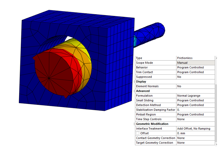
I have just selected Normal Lagrange and ran the simulation, however, it still penetrate the surface as shown below.
Is there any other option I should select or modify? I have attached my setting for frictionless contact.
Thank you very much in advance!

-
-
April 8, 2024 at 10:09 am
Stella Peloni
Ansys EmployeeHello,
It would be better the cube and the part of the beam have the same diameter. Additionally, the surfaces which take part in the contacts(target and contact), should have a refined meshing. You could have a better insight on the penetration (except for visual) by using Contact tool in your Solution branch. In this link, you can find some tips on how to avoid penetration. I think you will find helpful!
Kind Regards,
Stella
-
April 8, 2024 at 4:38 pm
kyungha.lee
SubscriberHi, Stella.
Thank you again for all the useful links and the information.
What I want to see is the effects of having a gap between the cube and the beam when they have slighlty different diameters.
Will it be possible to see this effect when I model the cube and the beam with the same diameter?
I have tried all the above solutions but when I auto-scaled, I could still see the penetration. The accleration I have applied is low so in real life, the model will not deform like that but I would like to model the simulation as closest to the real world as possible.
Kind regards
Kyung Ha Lee
-
-
- The topic ‘Prevent penetration of an object to other object using contact’ is closed to new replies.


-
5039
-
1749
-
1387
-
1248
-
1021

© 2026 Copyright ANSYS, Inc. All rights reserved.


