TAGGED: ansys-aqwa, aqwa, fender
-
-
March 19, 2024 at 2:52 pm
M. Namaki
SubscriberDear ANSYS/AQWA Community,
I am eager to connect with fellow users who may have experience with modeling a Torus Shaped Wave energy Converter (like Wavebob) attached to a spar-buoy and the WEC's Power Take-Off (PTO) in ANSYS/AQWA.
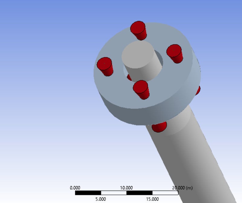
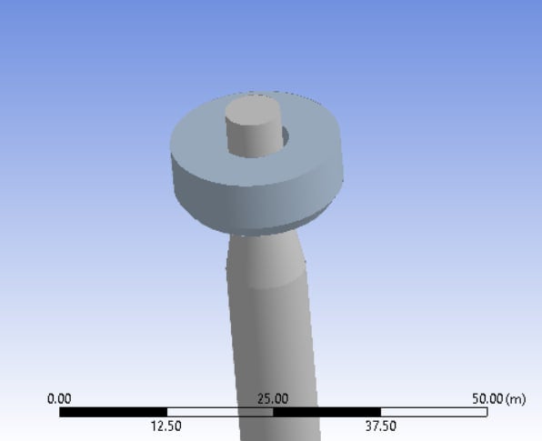
In my attempt to model the Torus Shaped WEC's PTO with fenders in AQWA, I'm facing challenges modeling a submerging Torus-shaped WEC with Fenders in AQWA. I encounter issues with disconnection of Fenders in z-direction and the WEC penetrating the structure and leave it due to the thin zero-thickness surface in AQWA. Additionally, the WEC's motion disrupts the fenders designed for it.
Additionally, I observed that the motions of the torus-shaped WEC were significantly less than those of the spar-buoy. This discrepancy resulted in issues with the fenders I designed, rendering them ineffective after a few seconds as the WEC seemingly disengages from the structure.
my main problem is in understanding your fenders' configurations and how you limited the WEC's motion in the X and Y directions relative to the structure so it will just have a relative motion in heave direction (something like modeling the guide-roller system between the WEC and the structure).
Thank you in advance for your time and assistance. I look forward to learning from the experiences of the ANSYS/AQWA community. -
March 20, 2024 at 10:01 am
Shuangxing Du
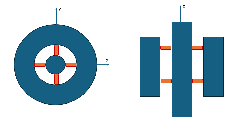
Ansys EmployeeTo allow the relative motions only along the spar local z-direction, please defined the pairs of fenders, which are fixed on torus-shaped WEC and the contacting surfaces are defined on spar, on two horizontal planes, as shown below
The fenders you defined which the fenders' axis is in relative vertical axis are still valid for modelling the PTO system. I wonder the sizes to these fenders could be bigger?
-
April 7, 2024 at 7:06 pm
M. Namaki
SubscriberThank you for your response.
but what kind of fenders do you think is better to allow the relative motions only along the spar local z-direction? omni-directional or one-direction only? and what about the fender properties? could you please help me in adjusting proper amounts for siffness coefficients (A to E), damping coefficient, friction coefficient and size?
-
-
April 7, 2024 at 6:25 pm
M. Namaki
Subscriber -
April 8, 2024 at 9:32 am
Shuangxing Du
Ansys EmployeeThe omni-directional fenders will be fine. The stiffness of fenders between Spar and WEC for allowing the relative motions along the spar axial direction could be set to ensure that the natural frequencies of the relative roll/pitch motions bweteen the spar and WEC is higher than the interested frequencies of the responses. For example, these natural frequencies are higher than the wave spectrum's finishing frequency (beyond it the wave energy is less than 0.5% of the total wave energy). The size could be slightly larger than the gap between the spar and WEC. The damping and friction coeeficients should be decided by the properties of your model.
-
April 8, 2024 at 11:21 pm
M. Namaki
SubscriberI’ve tryed it so many times but can't understand why it doesn’t work out for me?
I really appreciate your help.
I set the stiffness of the transverse fenders 10E+12 N/m which costed me a small time step of 0.001 s but the torus still goes far from the spar and I get the error blow:
HYDRODYNAMICALLY INTERACTING STRUCTURES HAVE MOVED TOO FAR FROM ANALYSIS POSITION MOVEMENT EXCEEDS 75% STOPPED AT TIME = 5.31.
I tryed it with a simple regular wave which did not have a very high amount of period and amplitude!
-
-
April 9, 2024 at 8:13 am
Shuangxing Du
Ansys EmployeeIs the relative motion between the torus and the spar mainly in the spar axial direction after using these fenders? Such large relative motion may also cause the error mentioned above.
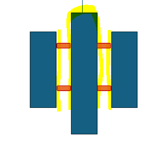
If the gap between torus and spar is small (about 1 to 2 times of mesh size), I wonder if you can make the surfaces in the gap (the highlighted parts as shown below) to be non-diffraction?
-
May 13, 2024 at 11:26 am
M. Namaki
Subscriberdear sxdu
I tried refining the mesh to about one third of the gap between torus WEC and spar structure but still the problem exists. tryed so many amounts for stiffness coefficients but it won't respond well! and by the way I don't know how to make some parts non-diffraction! I would appreciate if you could guide me through this matter.
I guess this problem was mentioned before in ansys forum and it seems it was solved but I just can't understand how?! the link is below:
/forum/forums/topic/ansys-aqwa-how-to-set-only-a-vertical-movement/
and I get these warnings too that I don't know how to solve and don't know if those are related to this relative vertical movement problem!
-
-
- The topic ‘Modeling a Torus Shaped WEC in ANSYS/AQWA for a Floating Platform’ is closed to new replies.


-
4613
-
1520
-
1386
-
1209
-
1021

© 2025 Copyright ANSYS, Inc. All rights reserved.


