-
-
March 6, 2024 at 5:11 am
Dheeraj Etta
SubscriberHi,
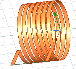
I am trying to simulate a basic air-core solenoid inductor with foil wire (as shown in the figure below) in maxwell 3D using eddy current solver.
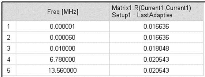
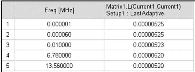
When I set current excitation (1A solid), also set eddy effects for copper coil and simulate it, the inductance value that I get makes some sense but the resistance value is completely off and it isn't even close to my analytical calculations. Theoretically, resistance should depend on frequency but the resistance values that I get are almost independent of frequency as shown in the table below.
Resistance values:
Inductance values:
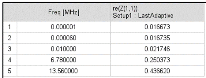
I have also simulated the same inductor in HFSS too and the results I get there completely makes sense and are closer to my calculations. Table below shows the resistance values with respect to frequency.
Resistance values (HFSS):
Not sure what wrong am I doing in my maxwell 3d simulations. Can someone please help me solve this issue?
-
March 6, 2024 at 3:52 pm
Reshmi Raghavan
Ansys EmployeeHello Dheeraj,
In maxwell please make sure the mesh used is refined at 13.56Mhz to caputure the current distribution and resistance of the wire.
-
March 6, 2024 at 4:30 pm
Dheeraj Etta
SubscriberHi Reshmi, Thanks for your response. Can you please elaborate on the preferred meshing configuration for these frequencies?
-
March 7, 2024 at 4:31 am
Reshmi Raghavan
Ansys EmployeeHello Dheeraj,
Based on the applied frequency the area through which the current flows in a coil will change due to the skin effect. Now if the mesh is not refined enough to capture the skin depth the resistance computed will not be correct. Maxwell does the volume meshing, so the skin depth has to be represented by th mesh element.
HFSS does a surface meshing and the surface behaviour can be captured very well.
When you are carrying out an analysis in eddy current simulation, mesh is created for the adaptive frequency mentioned in the Analysis setup. This mesh is used for the analysis of other frequency points. So make sure the adaptive frequency mentioned is closer to the maximum frequency.
-
March 7, 2024 at 4:40 am
Dheeraj Etta
SubscriberHi Reshmi,
Yes, my adaptive frequency was set to be 13.56MHz (which is the maximum frequency in my simulation) in the simulations shown above. Still, I don’t see good results for resistance values.
Do you think I should do an “Inside-Selection” mesh operation for copper wires and select length-based refinement with the maximum element length being set at skin depth @ 13.56 MHz? However, I think this is going to take a lot of computational time.
-
- The topic ‘Resistance and ohmic loss results don’t make sense in maxwell 3D’ is closed to new replies.


-
4838
-
1587
-
1386
-
1242
-
1021

© 2026 Copyright ANSYS, Inc. All rights reserved.


