TAGGED: 3d-maxwell-simulation, transient
-
-
March 5, 2024 at 12:57 am
-
March 6, 2024 at 3:32 pm
Reshmi Raghavan
Ansys EmployeeHello Zhan,
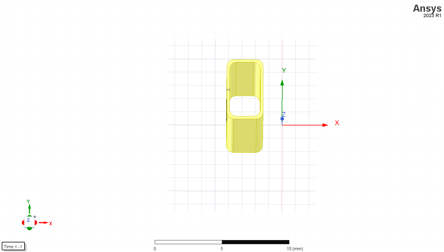
The approach used by you is correct. The model can be modelled in two ways.
1) As a single hollow cylinder representing the four layers in a single entity(total turn to be 250*4). This representation can be used if the gap between the layers is not suffeciently large.
2) Model four hollow cylinder representing each of the layer. If the gap between the layer is big in comaprison to the turns in the layer. A winding can be defined and four terminals(250 per turn) from each of the layer can be grouped inside this winding.
-
March 7, 2024 at 1:26 am
zcs19991114
SubscriberThank you for your answer.
The thickness of the model represented by the total thickness of the four-layer coil if I choose the first method?
-
-
March 7, 2024 at 3:55 am
Reshmi Raghavan
Ansys EmployeeHello Zhan,
Yes, you are correct.
-
- The topic ‘How to express multi-layer coil in Maxwell 3D?’ is closed to new replies.


- Three-Phase Voltage Imbalances in dual stator electric generator
- Link the Circuit to 3D Terminals
- Magnetic Dipole moment calculation
- Integration lines or U Axis Line for circular and rectangular ports
- Core Loss in ANSYS MAXWELL Eddy Current solution
- exporting and importing my Netlist for my external circuit
- Error of Metal Fraction in Icepak Classic.
- The unit of theta in Is*sin(2*pi*fre*Time+theta-2*pi/3)
- 2D transient simulation -torque issue
- Two way coupling for Maxwell and thermal problem

-
4613
-
1520
-
1386
-
1209
-
1021

© 2025 Copyright ANSYS, Inc. All rights reserved.


