-
-
January 5, 2024 at 4:00 am
Kirei
SubscriberDear all, Currently I am modeling an FSI analysis of a flapping wing. The case is the wing is flapped in the root with a prescribed oscillating motion and the water is flowing through the wing.
I was able to model the schematic in the workbench. I used the CFX solver for the CFD. However, I faced a problem in modeling the interface between the structure and the fluid region.
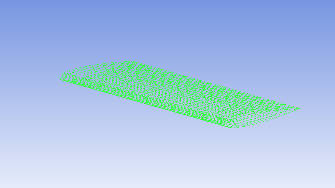
Here is the picture of the mesh of the CFD.
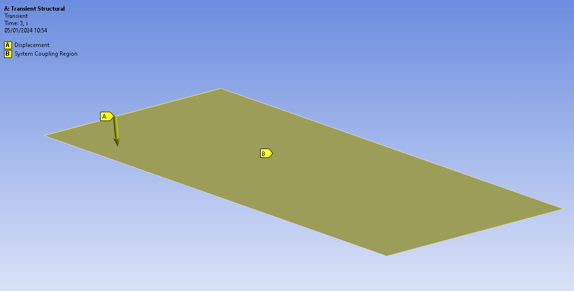
and here is a picture of the model of the wing's structure.
Because of the difference in the surface of the structure and CFD models, I always got an error regarding the mapping of the interface, as the CFD surface is an airfoil while the structure surface is a flat plate. I read from the System Coupling user guide that the absolute gap tolerance and face alignment can be changed, but I did not find it in the System Coupling workbench UI.
Does anyone have a solution for this problem? I wonder how to simulate a flapping wing with there is a difference in the interface of the CFD surface and structure surface.
-
January 9, 2024 at 3:24 pm
Rahul
Ansys Employee- Make sure FSI interfaces on fluid and solid sides overlap.
- Ideally both fluid is extracted from the solid, i.e. the same source geometry.
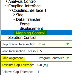
- Face alignment and absolute gap tolerance can be changed in standalone SC GUI under mapping control as shown below image. MappingControl (singleton) (ansys.com)
Please refer to following tutorial to know more about settings needed while performing CFX-Mechanical coupling: Oscillating Plate FSI Co-Simulation with Partial Setup Export from Workbench (CFX-Mechanical) (ansys.com)
Hope this helps!
-
- The topic ‘Question About Fluid-Structure Interaction Modeling in Ansys Workbench’ is closed to new replies.


-
2979
-
970
-
857
-
750
-
599

© 2025 Copyright ANSYS, Inc. All rights reserved.


