Ansys Assistant will be unavailable on the Learning Forum starting January 30. An upgraded version is coming soon. We apologize for any inconvenience and appreciate your patience. Stay tuned for updates.
Fluids

Fluids

Topics related to Fluent, CFX, Turbogrid and more.

Problems in Multiphase Flow

    • farizanluthfi
      Subscriber

      Dear all,


      I have been dealing with multiphase flow inside the helically-coiled tube. My case is going to validate the case from an experimental study. The first try is, I do simulation in the single-phase to get the initial solution then continue with multiphase flow.


      I set my simulation with Coupled solver and changed several URF to make it stable. But on the process, I have a message that my turbulent viscosity is limited to viscosity ratio and also temperature limited then turn the simulation into diverged with divergence detected in k, vof-1, and pressure coupled.


      I use RPI wall boiling model in my case with the second option (Non-equilibrium Boiling). In my BC, in the inlet I put the value of T.I: 4% with my hydraulic dia. and the outlet is gauge pressure 0. The heated wall is set up based on the heat flux in the experimental case, and I put adiabatic wall to ensure fully-developed flow when entered into the domain.


      Please give some recommendation on this particular problem. Thanks.


      Best Regards,


      Luthfi Ady Farizan Haryoko

    • Rob
      Forum Moderator

      Check mesh resolution (is it fine enough) & quality, inlet conditions plus the various material properties & operating conditions. Also check the time step you used - it may be too big. 


      As we've commented before, please include pictures. 

    • farizanluthfi
      Subscriber

      Dear Rwoolhou,


      Kindly refer to the attached image in this message, I have shown you several parameters inside of the domain.


      For inlet temperature in vapor area, I put my saturation value of the bulk flow. Also for water-liquid and water-vapor properties I specify with function of temperature using piecewise-linear option and for the standard state enthalphy, it is calculated from the saturation value of the fluid.


      FYI: I also changed my turbulent intensity from my previous simulation from 4% to 5%, but the result is still diverged with a message that mentioned about temperature limitied and diverged detected in AMG solver: k


      Appreciated for your highly concern and support. Thank you


      Best Regards, 


      Luthfi Ady Farizan Haryoko


    • DrAmine
      Ansys Employee

      Please ensure you have wall yplus larger then 30..40.

    • farizanluthfi
      Subscriber

      Please be advised that the wall yplus larger then 30-40 is cannot be adapted in my case due to the large difference of bulk temperature between the experimental and my own simulation. At that simulation, I have been established the outer wall as well, but the result is not quite significant.


      Highly appreciated for any other recommendation.


      Thanks,


      Best Regards,


      Luthfi Ady Farizan Haryoko

    • DrAmine
      Ansys Employee

      Check if the reference temperature under material panel corresponds to saturation temperature. Avoid fine mesh near the wall. Start as conservative as possible by ramping heat flux at walls and reducing vaporization mass urf. 

    • farizanluthfi
      Subscriber

      As my experience, I put the reference temperature corresponds to saturation temperature is resulting in diverged value. So I change the reference temperature into 298.15K. For URF, I also give some modification to the URF since the first iteration. In addition, the mesh near the wall is also acceptable.


      My question is, until what value we can reduce our URF and what is the most significant option that could help increase get convergence and the result could be comparable for validation purpose.


      Thank you,


      Best Regards,


      Luthfi Ady Farizan Haryoko 

    • DrAmine
      Ansys Employee
      As it is steady state run you can reduce all urfs wuth exception of energy equation for the pseudo transient coupled solver to lower values. The final result will be reached later but remains unaffected by the urfs.

      Still sure that you will need to coarse the near wall mesh.
    • farizanluthfi
      Subscriber

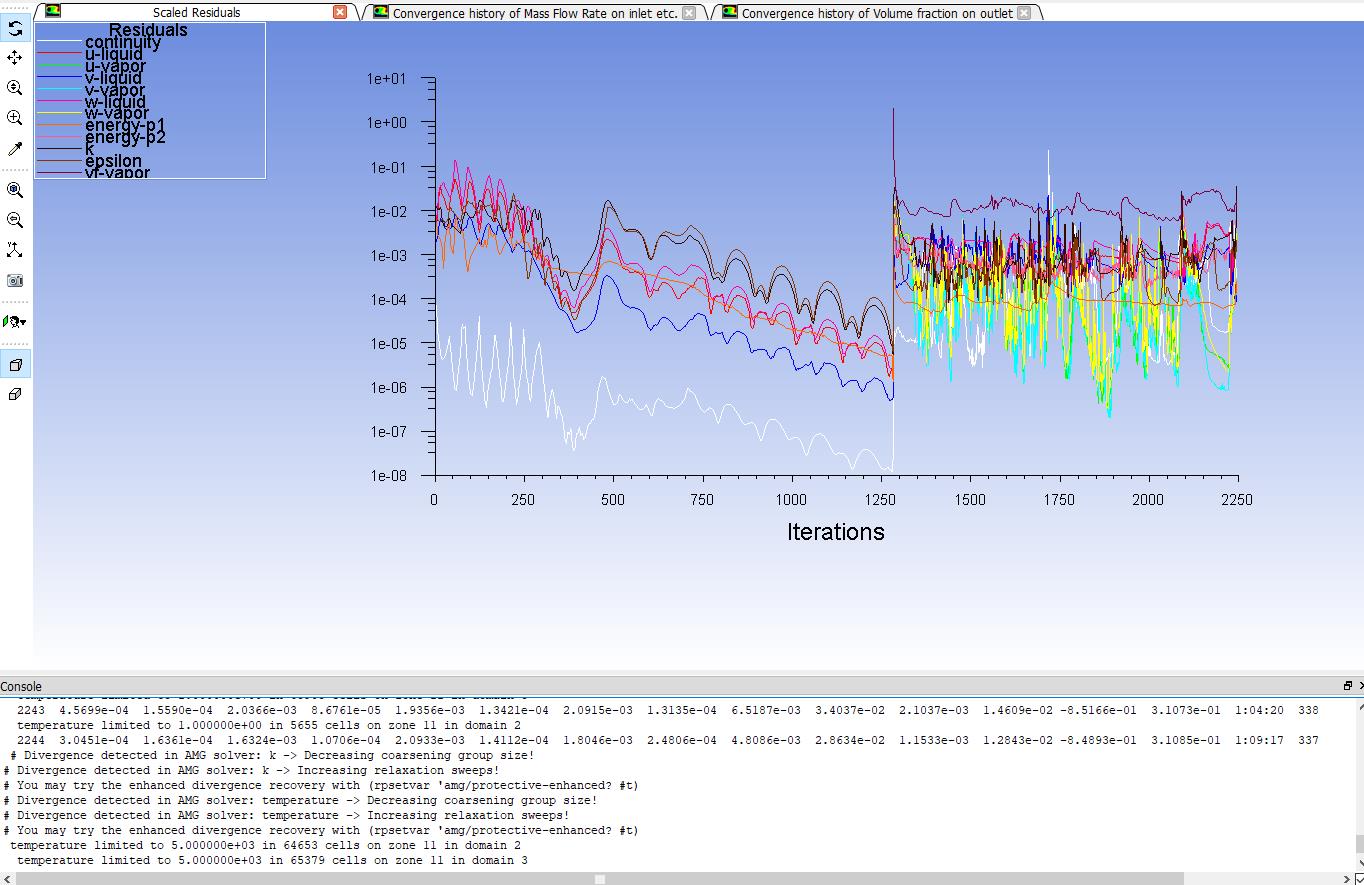
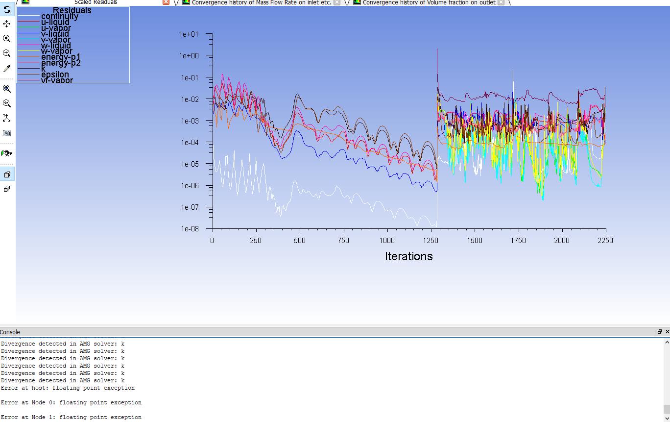
      I have been modified the URF with certain values and always get diverged for k and epsilon. Also, I have a warning message on turbulent viscosity limited and temperature limited in the FLUENT. I have been searched in the forum to overcome the issue but still have no significant result on it.


      Please noted for URF that I am using in the details below:


      Pressure & momentum: 0.25


      Density: 1


      Body forces: 0.5


      Vol.fraction: 0.3


      Vaporization mass: 0.5


      Turb. kinetic energy: 0.3


      Turb. dissipation rate: 0.3


      Turb. viscosity: 0.5


      Energy: 0.5


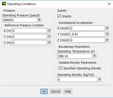
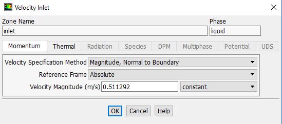
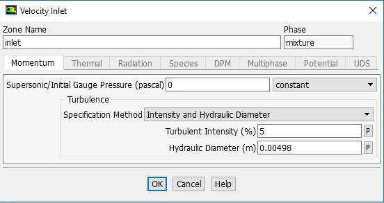
      For operating condition, I put my operating density is equivalent to the saturation value. I have also started my heat flux with 70% from the reported heat flux and now it's in ramping into 75%. For the discretization method, I have changed into second order for almost equation except for vol.fraction into QUICK.


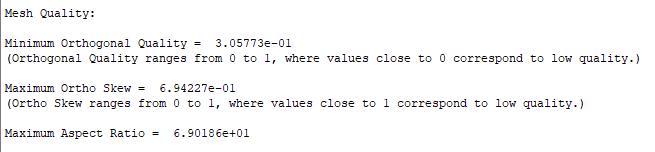
      Near-wall mesh based on my experience, it didn't help much for the expected result from the simulation.


      Please give me any direction for this method on how to solve multiphase flow boiling heat transfer.


      Thanks,


      Best Regards,


      Luthfi Ady Farizan Haryoko

    • DrAmine
      Ansys Employee
      Do not reduce energy URF for non pseudo transient approach. Try ramp the heat flux and coarsen the mesh. How does you geo look like? Please highlight in the picture the gravity direction.
    • farizanluthfi
      Subscriber

      I am running the simulation for pseudo transient approach, because when I just use steady-state, it will get diverged easily. I have attached the pics in the message below. Thank you so much Sir.


      Best Regards,


      Luthfi Ady Farizan Haryoko


      It could be seen in the pics that the gravity is in Y-axis direction. The inlet region is in the below helical coil and the outlet region is in the upper helical coil. The adiabatic length is applied for making fully-developed flow in the domain. I have been employed the adiabatic length in the extended region for inlet and outlet.

    • DrAmine
      Ansys Employee

      That is not really an application range for RPI Boiling method which has been designed and validated for vertical heater. The wall heat flux partitionier will work. However if you have horizontal heated walls, is more likely that you have pool boiling than forced convection boiling. The correlations for the submodels of the RPI model were derived for forced convection cases

    • farizanluthfi
      Subscriber

      According to some publications that I've been studied, RPI boiling method could be utilized for the helically-coiled tube as their interest, and it still works basically. Meanwhile the horizontal one is not a heated wall, it is just an adiabatic wall to ensure fully-developed flow inside the domain. The heated wall is the helical tube wall with constant heat flux in the wall to generate some bubbles for boiling case.


      If you have another solution what should I choose to carry on the boiling case for the helical tube, please let me know, I will surely follow your consideration.


      Thank you.


      Best Regards,


      Luthfi Ady Farizan Haryoko

    • DrAmine
      Ansys Employee
      I am involved in RIP funded works and I am talking from experience . The fact that it has been used does not mean it will work all time. As ANSYS stuff I cannot have a look into your case but end up with the already provided suggestions: coarsening the near wall mesh and looking into the ranges of submodels correlations.
Viewing 13 reply threads
  • The topic ‘Problems in Multiphase Flow’ is closed to new replies.
[bingo_chatbox]