General Mechanical

General Mechanical

Topics related to Mechanical Enterprise, Motion, Additive Print and more.

shell to solid connection with thermal load

    • dave
      Subscriber

      Hi, I am familiar with using edge to face contact to connect shell to solid elements in Mechanical.  This method has worked successfully for transferring mechanical loads.  I am having issues when I apply a temperature to the model.  Instead of free thermal expansion, I get a stress discontinuity at the interface.

      Can anyone offer any advise on this please?

    • Akshay Maniyar
      Ansys Employee

      Hi Dave,

      Solid elements have 3 dofs per node (displacements in 3 orthogonal directions), whereas shell elements have 6 dofs (3 displacements, 3 rotations). Contact must be used between the 3D body and the shell. MPC formulation is most advisable. The contact surface/edge should be on the shell side and the target surface must be on the solid side. Constraint type options (couple U to ROT / uncouple U to ROT) allow to define how the dofs are coupled.

      Thanks,

      Akshay Maniyar

    • dave
      Subscriber

      Hi Akshay, many thanks for your reply, which is indeed very helpful.

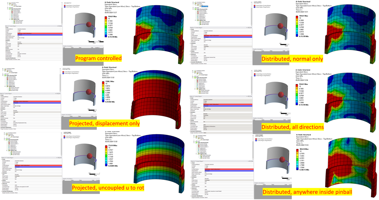
      The contact surface /target edge are as you suggest.  I updated the contact formulation from 'program controlled' to MPC.  I went through and tried each of the six constriant type options.  The results are in the picture below.

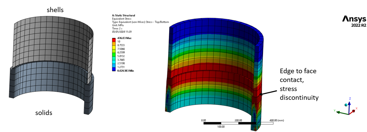
      The stress discontinutiy is very high using the program controlled option (194.6 MPa), however using the 'projected, uncoupled u to rot' gives the lowest overall magnitude at the discontinuity (25.6 MPa).

      I looked in the help file, the definition given is thus,

      "Projected, Uncoupled U to ROT

      The rotational and displacement constraints will not be coupled together. This option can model situations where the surface body edges line up well and a moment is not created from the physical surface body positions. Thus it is most accurate for the constraints to leave the displacements/rotations uncoupled. This provides an answer which is closer to a matching mesh solution. Using a coupled constraint causes artificial constraints to be added causing an inaccurate solution."

      I want to make sure I am using the correct option.  The results suggest the behaviour is reasonable using 'projected, uncoupled u to rot'.   In my main analysis, I will make sure the shell to solid transition is sufficiently remote from the region of interest.  Is there anything else to be aware of by using this option?  Is there a any risk this option might be under constrained?

      Thanks again,

      Dave


    • peteroznewman
      Subscriber

      Hi Dave,

      You might find this discussion has some relevant information.

    • dave
      Subscriber

      To summarise, for anyone else that stumbles across this thread in future.

      1. Shell to solid connections using contact with the MPC formulation work well to analyse cases with forces, moments, pressure loads etc.
      2. Avoid shell to solid connections in models with temperatures applied, as the connection can create over constraint due to thermal expansion, particularly due to expansion in the through thickness direction.
      3. If a shell to solid connection is used, make sure it is sufficiently remote from the region of interest.
      4. Using the MPC with "projected, uncoupled u to rot" option means that separate constraint equations are setup for the displacements and the rotations.  In a test case with uniform temperature appplied, this option lead to the lowest stress discontinuity at the connection between the shell and the solid elements. 
      5. I found a bit more information here on the MPC formulations here, see slide 44-46:
        https://www.researchgate.net/profile/Musavir_Bashir/post/how_can_I_solve_such_type_of_problem_in_ansys_CFD/attachment/5ac9a4be4cde260d15d76e9f/AS%3A613009869258752%401523164350093/download/ansys+mech+structural.pdf
      6. Shell elements have a discrete number of integration points through thickness, these can be used to apply temperatures through thickness.  To match the number of points through thickness, set the number of integration points for the shell element equal to the number of solid element nodes through thickness.  The number of integration points needs to be an odd number to ensure there is one point in the centre of the shell.
      7. Refer to the other thread as advised by Peter in the above post as it contains some really useful information and test cases.
    • deepesh.p.gurdasani
      Subscriber

      In general, does the MPC contact transfer all 6 DOFs of 2D body to 3D body ? or its just 3 Translational DOFs ?

    • Akshay Maniyar
      Ansys Employee

      Hi Deepesh,

      Please start a new thread for new questions. It will be easy for other users to refer too.

      Thanks,

      Akshay Maniyar


Viewing 6 reply threads
  • The topic ‘shell to solid connection with thermal load’ is closed to new replies.