TAGGED: mechanical, torque, torque-calculation, transient
-
-
December 25, 2023 at 9:44 pm
rnegrete
SubscriberHi. I have an eccentric wheel mechanism and I want to find the torque that the wheel can produce. It has a frame that has a body-to ground fixed joint that holds the mechanism. The frame is connected to a piston with a translational body-to-body joint, which is connected to a rod with a body-to-body revolute joint, which is connected to a eccentric pin on the wheel, again by a revolute body-to-body joint, finally, the center of the wheel is connected to the frame with another revolute body-to-body joint. The piston is moved through a system-coupling interaction with Fluent. Everything is working ok. I can run the simulation and get all the info I need except the torque of the wheel. I can get the displacement through a deformation result but I cant get the force. I tried using a probe for force and moment reaction but I can only use the geometry selection location method for a surface and the results don't make much sense to me. I have set everything to Yes in calculation settings - output controls. I want to have a transient analysis where I can calculate the torque, the displacement and the energy that I can generate with the wheel throughout the oscillation of the piston. What can I do to get these results? Many thanks
-
December 26, 2023 at 11:03 pm
peteroznewman
SubscriberYou can request the force going through the revolute joint on the arm of the wheel and the connecting rod. A similar force goes through the revolute at the other end of the connecting rod. With some vector math, calculate the angle between the connecting rod and the radial vector from the center of the circle to the point on the arm. Multiply the Total Force by the sine of the angle to get the tangential component of force and multiply by the radius to the point on the arm to get the Torque. When the angle of the connecting rod is 0 or 180 degrees, the Torque is zero because the sine is zero.
-
December 27, 2023 at 6:49 pm
rnegrete
SubscriberThank you Peter.Â
The trouble that I'm having is that I'm getting the force results with the "Location Method - Geometry" and then selecting the "Surface" of the frame where the wheel spins and the result is not making much sense to me, so I was trying to use another "Location Method" to see if the result makes more sense. If I get the force from the eccentric pin to the connecting rod I get the same results because I'm using the same location method. In the end, I want displacement, force, torque, work, power and energy over an entire oscillation. I'm also trying to work my way back from energy to force but my energy plot has more peaks and valleys than what I think it should... Can you point in any other direction to get these results, or to work my way from another result to these so I can compare and make better sense of them?Â
Many thanks!
-
December 27, 2023 at 10:10 pm
peteroznewman
Subscriber -
December 28, 2023 at 1:06 am
peteroznewman
SubscriberYou say a CFD model creates a force that causes an oscillating vertical displacement of the slider, which causes the wheel to spin. Is it a float at the surface of water with waves that causes the oscillating vertical displacement? What is the purpose of spinning the wheel? Is it to create electricity by spinning a rotor in a generator? Is it to turn a fan blade to blow air? In both these examples, the item connected to the wheel requires a torque to spin the shaft, this item can generically be called a torque load. Torque loads often have a Torque-Speed operating curve. For example it takes only a small torque to spin a fan blade at a low angular velocity, but a high torque to spin a fan blade at a high speed.
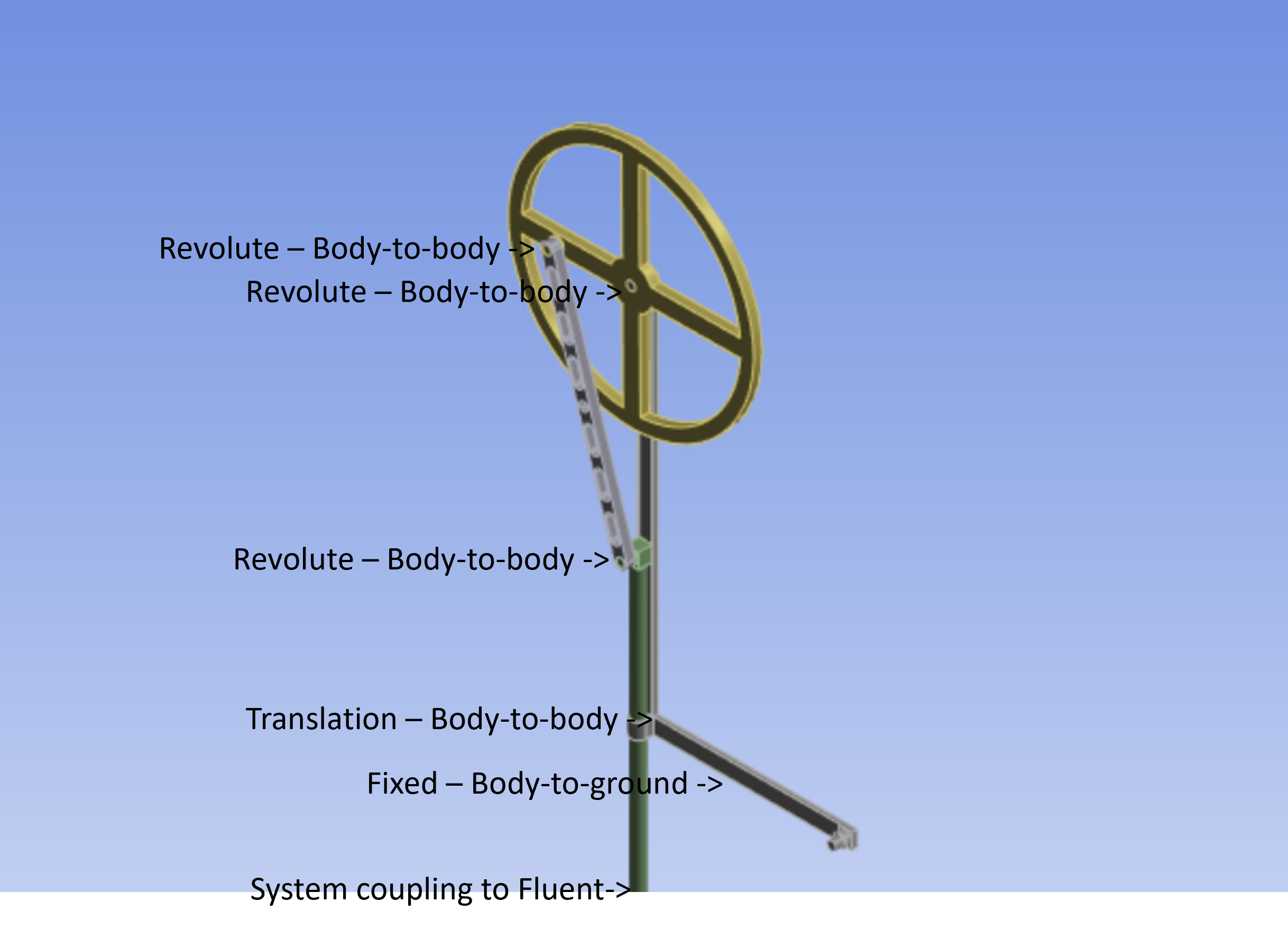
It may be helpful to describe the overall system as it seems that the torque load is missing from your model. You can easily add a constant torque load to the revolute joint at the center of the wheel, or use a function to implement a speed-dependent torque.
One important characteristic of the wheel is a large mass moment of inertia because the angular momentum of the wheel is needed to continue the spinning motion of the wheel past the two zero-torque angles of the wheel: top-dead-center and bottom-dead-center. With no external torque load, the only need for torque is to accelerate the angular velocity of the wheel.
The mechanism reminds me of an internal combustion engine (ICE) that has a piston that oscillates along the cylinder, driven by force from the pressure caused by burning fuel. If the torque load is too large, the engine will stall. If you have driven a stick-shift and let the clutch out too fast or forgot to put the transmission into first gear, the crankshaft will just stop turning as the torque load exceeds the torque delivered by the engine. In a similar way, an excessive torque load on a wave driven mechanism will have the wheel stop turning and the float will just be submerged as the wave passes by.
-
December 28, 2023 at 6:04 pm
rnegrete
SubscriberÂ
The oscillation coming from Fluent is caused by a float at the surface of the water passing through waves. The purpose of the wheel is to generate electricity.
Â
Here´s a screenshot of what I was trying to do, and I could't see any options for the yellow part:
Â
I then did what you said about draging the joint into the solution and got:
This result is making much more sense. It seems that the amplitude of the oscillation coming from Fluent is slightly bigger than that of the Wheel so a lot of the energy is going into bending the connecting rod and then it un-bends and bends again repeatedly making those peaks in the force plot. I was inspecting the wave amplitude and the float displacement in CFD Post and the wave’s distance from the crest to the free surface level without wave is a bit larger than the distance from the free surface to the trough so that would also explain why the peaks are larger on the crest than the trough. BO is Buoyant Object
Â
Right now I’m simulating the first oscillation trying to make sure that I get enough energy to make the first spin from a resting starting point, I will the add the friction of the various joints and then I will see how the system behaves carrying some momentum. Finally I will play with some resistance from the generator and increasing and decreasing the mass of the wheel to understand a bit better the behavior with the momentum and the resistance so I can paint a better picture of the torque speed operating curve as you suggest.
Â
Thank you so much for your insights!
Â
-
-
- The topic ‘How to calculate torque on an eccentric wheel in a transient analys’ is closed to new replies.
-
6455
-
1906
-
1457
-
1308
-
1022
© 2026 Copyright ANSYS, Inc. All rights reserved.


