We’re updating our badges platform. Badge issuance is temporarily paused, but all completions are being recorded and will be fulfilled once the platform is live. Thank you for your patience.
Fluids

Fluids

Topics related to Fluent, CFX, Turbogrid and more.

How to simulate single point mooring buoy with an attached FPSO in Aqwa

    • kingdsystems
      Subscriber

      I am fairly new in Aqwa, even though I have done a considerable amount simulations with it. I am trying to design a single point mooring buoy with FPSO attached to it. I have search the internet for resource materials that can help find a way around it, though i haven't seen any. 

      My questions are:

      1) How do i model this structure in CAD, will it be individually or together in the same workspace.

      2) I have done mooring analysis on single structures, in this case, how do i carry out the mooring especially, connecting the hawser and avoiding collision.

      I hope, my questions are understable and will appreciate a quick response in order to complete this research.

      Thanks

    • Mike Pettit
      Ansys Employee

      Hello,

      Aqwa can simulate multiple structures in the same analysis. By default, the calculation will include hydrodynamic interaction between the structures, so (for example) the radiated waves due to the motion of the FPSO will affect the motion of the buoy, and vice versa.

      The geometry should contain both the FPSO and buoy together in a single CAD workspace. The Ansys geometry editors are all capable of combining multiple files into a single assembly, so if you have separate CAD files for FPSO and buoy you can easily import these into one model.

      To model the hawser, you should create a cable with structure-to-structure connectivity. You can use any of the standard Aqwa cable types (linear, nonlinear polynomial, steel wire, nonlinear catenary).

      For collisions between the FPSO and buoy: Aqwa does not automatically detect collisions between structures, but we can use fenders to model any contact. Add a fender under Connections, define the size and stiffness/damping/friction coefficients, then orientate the fender axes and contact axes so that the fender X and contact X directions are pointing towards each other. The fender 'Initial Attachment Point Separation' value will show the normal distance between the fender and contact plane. Be aware that the contact plane extends to infinity; you cannot define a contact plane that only covers a limited region.

      I hope this helps!

      Mike

      • Fatma Helal
        Subscriber

        Hello I'm a marine engineer i have to simulate SPM buoy attached to drill ship in Aqwa but I can't find any videos or resources to help if you can help me i will be very grateful for that ????????

    • kingdsystems
      Subscriber

      Thanks for your response. 

    • kingdsystems
      Subscriber

      This is what i wanted but i notice in the diffraction, the pressure and motion solution does not include both structures on the same animation. 

      In this case, what should i do or is it normal? Like is earlier mentioned, i am new to multi-body simulation in Aqwa.

      If there is a e-documents or videos that describes a detailed procedures for achieving this tasks, i will be glad to have them.

    • Mike Pettit
      Ansys Employee

      Hello,

      It sounds like the FPSO and buoy are not in an interacting structure group. In this case, Aqwa will calculate an independent hydrodynamic database for each structure, which is why you are not able to plot e.g. the Pressures and Motions wave surface elevation for both structures at the same time.

      To resolve this, click on Structure Selection under the Hydrodynamic Diffraction analysis. Confirm that 'Interacting Structure Group 1' is showing 'None'. Click 'None', then click on the structures in the Graphical Window, while holding down the Ctrl key to multi-select. Then click 'Apply', and the 'Interacting Structure Group 1' field should change to 'All'. Then re-run the Hydrodynamic Diffraction analysis.

      Mike

    • kingdsystems
      Subscriber


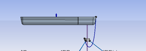
      Thank you very much, Mike. I was able to scale through that but i ran into multiple problems. Why is the buoy sinking instead of floating in the hydrodynamic response animation window.  

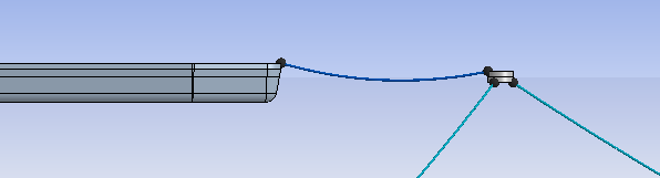
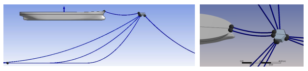
      Before the hydrodynamic response solution
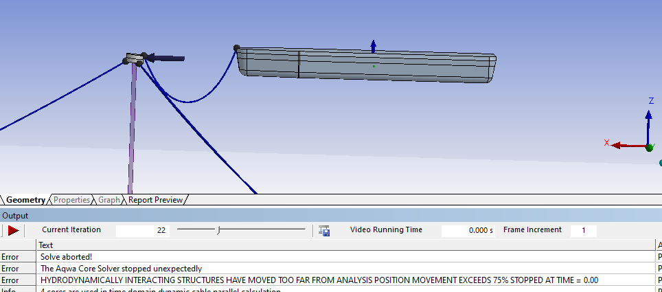
      After the solution.

      Also i noticed that my ship actually moved, maybe because i add current velocity (1m/s) in the solution. 

      I also got multiple error warnings:

      1) Hydrodynamically interacting structures have move significantly from the analysis position result are inaccurate - movement exceeds 50%. 

      2) CABLE DYNAMICS- WARNING - SLACK CABLE #3: The minimum allowable tension for the line is 64200.0. The minimum calculated tension for this line is 52928.6 move attachments further apart or shorten line. The cable 3 here is the hawser (line connecting the ship to the buoy)

      3) I also noticed that my hawser cable parabolic downward

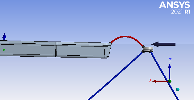
      4) Mass/displaced mass significantly different for structure #2. difference = -19.5%. My structure 2 is the Ship.

      Mass/displaced mass significantly different for structure #2. difference = -51.9%. My structure 1 is the buoy.

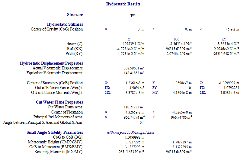
      This is the hydrostatic results obtained from the buoy:

      Thanks for any idea that will help me solve this problems.

    • kingdsystems
      Subscriber

      Hi Mike, compliment of the season, 

      Goodnews! I was able to find my way around some of those challenges I posted earlier but I did run into another serious problem, "hydrodynamically interacting structures have moved too far from the analysis position movement exceeds 75%".

      From the animation, the FPSO actually moved, colliding with the buoy. I guess that's part of the problem.

      Please I need your help. I have been stock here for days without any solution.


      Thanks.

    • Mike Pettit
      Ansys Employee

      Hello,

      Sorry for the delayed reply - I've been on annual leave over the holidays. I'm glad to hear that you managed to resolve the issues from your previous post.

      For the error of 'hydrodynamically interacting structures have moved too far', it helps to understand the hydrodynamic interaction calculation in the Hydrodynamic Diffraction analysis. When we perform the analysis for a group of interacting structures, the frequency-dependent added mass and radiation damping matrices are calculated to include the hydrodynamic interaction effects between each structure. However, these matrices are only strictly valid for the structures in their relative analysis positions. In other words: if the distance between the structures increases in the time domain, we would expect the radiation effect to reduce, but the matrices are not recalculated, so the radiation effect stays the same. Therefore the time domain Aqwa solver issues warnings/errors as the relative positions of the structures change in time. If the relative positions change too much, the Aqwa solver stops to prevent very inaccurate results.

      Looking at the error message in your screenshot, the part 'stopped at time = 0.00' indicates that the relative positions have already changed too much when the time domain calculation starts, i.e. the movement is occurring during the upstream Hydrodynamic Response stability analysis. To try and fix the problem, you could write down the structure positions at the end of the stability analysis (when the structures are in equilibrium), move the structures in the geometry editor to these positions, then re-run the Hydrodynamic Diffraction analysis. In this way you can ensure that the hydrodynamic interaction effects are more accurate in the time domain, and the Aqwa solver should allow the analysis to run.

      I hope this helps!

      Mike

    • kingdsystems
      Subscriber

      Thank you Mike. Happy new year. 

      How can I obtain the structure positions at the end of the stability analysis. Please kindly explain this.

      Thank you. 

      • Mike Pettit
        Ansys Employee

        Happy new year to you too!

        Add a result of Structure Motions > Structure Position > Actual Response to the stability analysis solution. Click on 'Structure Position, Actual Response' and set the Component to Global X, then right-click on this object in the Outline tree and Duplicate. In the copy, set Component to Global Y. Keep duplicating and setting Component until you have all of the degrees of freedom Global X/Y/Z/RX/RY/RZ included on the graph. Evaluate the result, then click on 'Parameters vs Iteration Step', and in the Details panel the 'Final Value' fields will show the Global X/Y/Z/RX/RY/RZ COG positions/rotations at equilibrium. The difference between 'Initial Value' and 'Final Value' for each freedom is the offset that you should apply in the geometry editor.

        Mike

        • Mike Pettit
          Ansys Employee

          I should mention - if you are using Release 2023 R1 or newer, you could add a Part Transform to the parts in Aqwa Workbench. This saves you modifying the geometry, and makes it easier to define the positions/rotations.

          Mike

Viewing 8 reply threads
  • The topic ‘How to simulate single point mooring buoy with an attached FPSO in Aqwa’ is closed to new replies.