-
-
December 14, 2023 at 5:59 pm
wallybanger
SubscriberI have been working at this for hours with no luck. I have a large assembly controled by parameters in Catia. I need to be able to update the model and run different cases in Ansys but I don't want to have to redo the model 9 times for each case. That will be WAY too time intensive. For the life of me, I can't get any sort of parameter linking or bidirectional design to work between Catia and Ansys. These are my geometry settings:

I would gladly ready the help/instructions/tech info but I can't find anything. I don't even know what to search for as everything I have tried yeilds no results. Can someone help me please? -
December 15, 2023 at 3:28 am
peteroznewman
SubscriberMike,
I haven't used the Catia-Ansys CAD interface, but I have used the NX-Ansys interface in the past. Now when I want to have any kind of parametric interface between CAD and Ansys Workbench, I use either DesignModeler or SpaceClaim because only those CAD programs (and Discovery now I suppose) support Multibody Parts in Ansys Workbench. Multibody parts are useful for meshing or changing materials without needing any bonded contact. But maybe you don't need Multibody parts support.
It looks like you have two revolute joint angles and you want to assemble the parts at three levels: -45, 0 and 45 degrees, for a total of 9 configurations. If you use Revolute joints, note that there is an Initial Position field that can be set to Override. That means you can bring in a single configuration: the (0,0) angle from Catia, and build the model in Mechanical. Then you can copy the model 8 times and Override the revolute Inital Position angles in each of the copies to set the other 8 configurations.
-
December 15, 2023 at 8:13 am
wallybanger
SubscriberHi Peter, thanks for the reply.
The image I showed was just to attract attention and as a general idea. I have a large, complex model that is driven with a skeleton, parameters and laws in Catia. Modifying it in design modeler or spaceclaim wouldn’t be so easy. I suppose I could import a whole ton of points and then try to reassemble each component but that sounds like way too much work.
I’ve done a whole bunch of reading and it sounds like the bi-directional connection between Catia and Ansys is basically impossible so I’m giving up on that avenue.At this point I’m guessing the easiest thing to do would be to make changes to my model, import each change and then somehow link the cases in Ansys Workbench. Is that correct? Do I have to turn off the model updates for each static structural instance in the workbench? I’d be happy to do the reading about this but I don’t know where to start.
As for modeling multi-body parts, I wasn't having much luck getting things to transfer properly to mechanical. I think it may be easier to bring the bodies in from a catia assembly and just use connections in mechanical.... unless you can tell me a reason why that isn't the best way to do things....
-
December 15, 2023 at 5:37 pm
peteroznewman
SubscriberMike,
Note that there are two Catia-Ansys CAD interfaces: “Reader Only” and “Associative Geometry Interface”.
I assume you were using the latter. The former is not associative, it is a one-way reader.
Did you read the Ansys Help entry?
The CATIA V5 associative geometry interface requires that the following software be installed and running:
Compatible version of CATIA V5 CAD program (V5–6R2020, V5–6R2021, V5-6R2022).
DSLS configured with a CATIA V5 (MD2, HD2, or ME2) license.
CADNexus CAPRI CAE Gateway V3.90.0
Do you have all that installed? The associative interface defininitely support parameters.
Ansys-Catia support Versions: V5R2 — V5–6R2022 of Catia. Are you in that range?
In order for Workbench to send parameters to Catia and get back the modified solid, surface and line bodies, you must have used the Prefix DS or ANS in Catia to name the parameters as shown in the Workbench Geometry Properties.
Have you named the Parameters with a DS Prefix?
Hidden parts will not be imported.
Using Parameters with CATIA V5 (CADNexus CAPRI CAE Gateway ) —
Parameter names contain the entire CATIA Assembly Name and Part Name.
Parameters are shown at the assembly level, under the Details of Geometry branch in the Ansys Mechanical application.
Embedded spaces should not be used in the Assembly Name or the Part Name to ensure compatibility with the DesignModeler Parameter Manager.
Have you removed any spaces in the Parameter names?
Finally, if you were expecting Joints defined in Catia to be imported, that is not supported. You only get the geometry. Once the geometry comes over, you define joints and contacts in Ansys Mechanical.
Say there is a parameter such as DS_linklen1 in Catia that is set to a value of 24 and controls the length of link 1 in Catia. That parameter will be available in Ansys Workbench. If you look in the Table of Design Points, you will see a row with a 24 in it under the DS_linklen1 Input Parameter. If you create a new row in the Table of Design Points and type a 36 in that column and click the Update All Design Points, Workbench will automatically start Catia in batch mode, rebuild the assembly using 36 for DS_linklen1 and pull that geometry into Workbench, then Mechanical will attach the native Ansys Joints to the face that is now on the longer link and run the Analysis and populate any results marked as output parameters to the Table of Design Points in Workbench.
If none of the Catia parameters change the shape of any geometry, but only relocate/reorient parts, then there is less value in the associative interface.
Good luck!
-
December 15, 2023 at 7:39 pm
wallybanger
SubscriberHey Peter, thanks again for the info.
It was not immediately clear that the CADNexus CAPRI CAE Gateway was required for the bi-directional interface. It's frusterating that a 3rd party plugin is needed but I digress.
In Catia, bugs never really go away, they just change so the art is trying to find a version with the least bugs or at least no bugs in the modules you use the most. I'm currently on V5R20. It would be possible but not desireable to move to V5R21 and I think there are interfaces that will work with V5R21 but possibly not with Ansys 2023R1. I'm honestly thinking the whole CAE Gateway is more trouble than it's worth.I started looking closer at space claim. Correct me if I'm wrong but it should be possible to manage the assembly from space claim with parameters if I set it up correctly and possibly use some scripting, is that correct? I wouldn't be changing any body features (holes, pads, cuts, etc), I would only be moving components in 3D space. Rearranging the assembly.
It's interesting what you were saying about the reader pulling in DS_ parameters because I actually have seen that with a test assembly that I made but quickly realized that it wasn't good for much. It's not overly useful because, as far as I can tell, geometry can't be updated from the cad files. Does what you're saying about the coordinate systems still apply if I manage the assembly in Space Claim? Can the coordinate system of a joint be made to follow the space claim coordinate system of a part? Do parts have coordinate systems in Ansys or would one need to be made for each part? Playing with space claim a little bit actually made me thing this is possible... it's actually fairly easy to use to recreate all of the joints for the assembly. Would you recommend I do this sort of work in Space Claim or Design Modeler or is it possible in Mechanical? -
December 16, 2023 at 10:05 pm
peteroznewman
SubscriberSince you don’t need to change the part goemetry, only reorient/relocate parts, I refer you back to my original suggestion of using the Joint Override feature and copying the analysis to create the 9 configurations.
If it can’t all be done with Joints, Workbench has a Part Transform capability when merging Mechanical Models into an assembly Mechanical Model. See my reply in this discussion.
-
December 19, 2023 at 7:23 pm
wallybanger
SubscriberOK, I see what you’re getting at and this is a good idea. The only problem with it is that I have 2 tierods that are free in space. The inner ends of these tierods are connected to the steering system but the outboard ends are fixed in space using frictionless support on a sperical surface of a balljoint.
Is there any way to define the position of the free ends using coordinates? Can I join to centre of the balls to fixed points or something like that? I don’t have any of the suspension geometry in the model to control the position of the ends of these tierods so I would need to do it with coordinates. -
December 19, 2023 at 10:58 pm
-
December 20, 2023 at 2:46 am
wallybanger
SubscriberI'm getting the impression that I can only do what I want to do if I have solid geometry for every single part in the assembly, which is disappointing.
-
December 20, 2023 at 2:52 pm
-
December 20, 2023 at 10:46 pm
wallybanger
SubscriberNo!! I didn't know part transforms were a thing. That looks like a very helpful feature. It doesn't allow me to do exactly what I want but it might get me close. I would prefer to locate the ball end using xyz coordinates but I'll play with this and see what I can do.
I was looking to see if Mechanical would allow me to pull in points and lines etc but I couldn't figure out how to make that work.
Thanks for all the help.
-
December 23, 2023 at 12:30 am
wallybanger
SubscriberOK, this is getting REALLY frusterating. I can NOT make this software do what I want it to do.
I have completely rebuilt my model with geometry for everything. I have joints set up. I can "configure" my joint and see it doing what I want it to do.
How do I set this joint in different positions and have it move to where I want it? The initial position Override is not functioning and I’m getting upset. I can set limits and move the joint to those limits but then I can't get it back to the "0" point.
Part Transform doesn't move geometry according to joints so it's basically useless.
If this software seriously isn’t capable of doing this REALLY simple thing then I have wasted 2 months of my time and will need to look at different analysis software. This shouldn’t be so hard to do. -
December 23, 2023 at 5:12 pm
peteroznewman
Subscriber
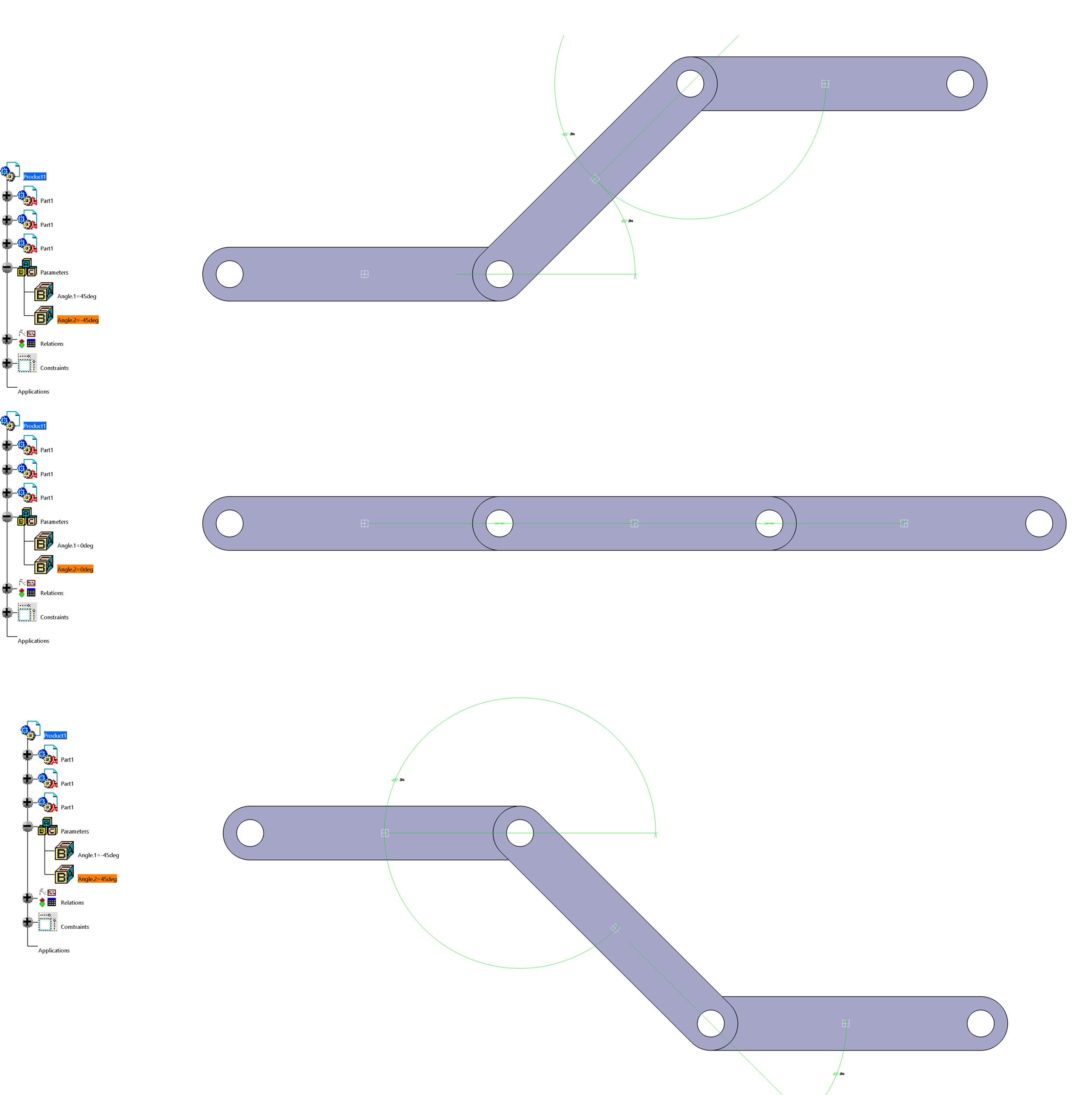
Mike, I’m sorry your search for a workflow to build the model you want is so frustrating. The simple example at the start of the discussion did not capture a feature I overlooked because it is a chain where the third body’s position in space is determined by just two revolute angles.
I created a slider-crank mechanism, where the position of the connecting rod is not so easily defined. In this example, assembly constraints in SpaceClaim keep the parts correctly assembled as the crank rotates using the Move tool.
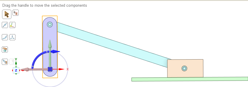
I have not figured out how to rotate the crank using a parameter because SC does not pop up a Parameter button the way it does when body faces are moved.
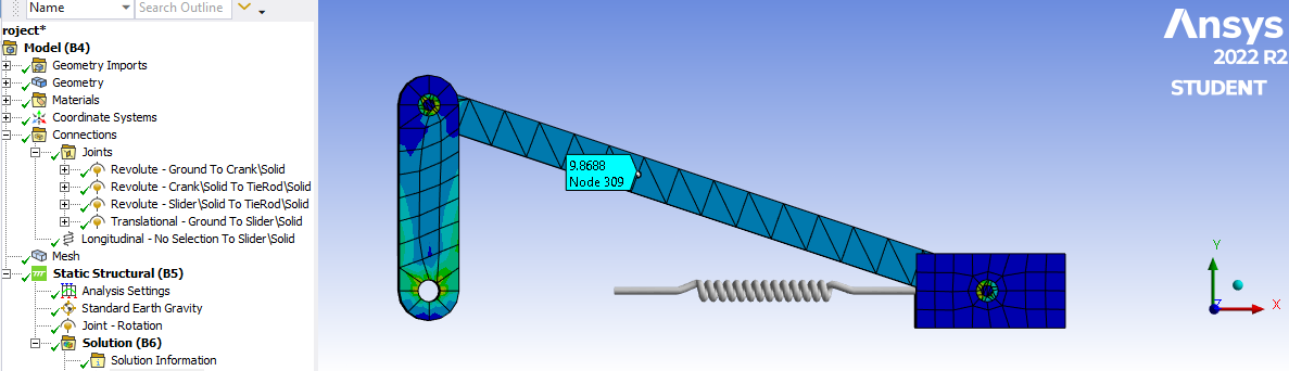
In Static Structural, I created joints to connect the bodies so loads can be transferred through the parts. I added a spring to add some load to the mechanism. The spring is preloaded by defining the Free Length of the spring. The force in the spring is calculated as the spring length minus the free length multiplied by the spring rate. In that way, when the crank rotates to a new angle, there will be more or less force as the spring length changes.
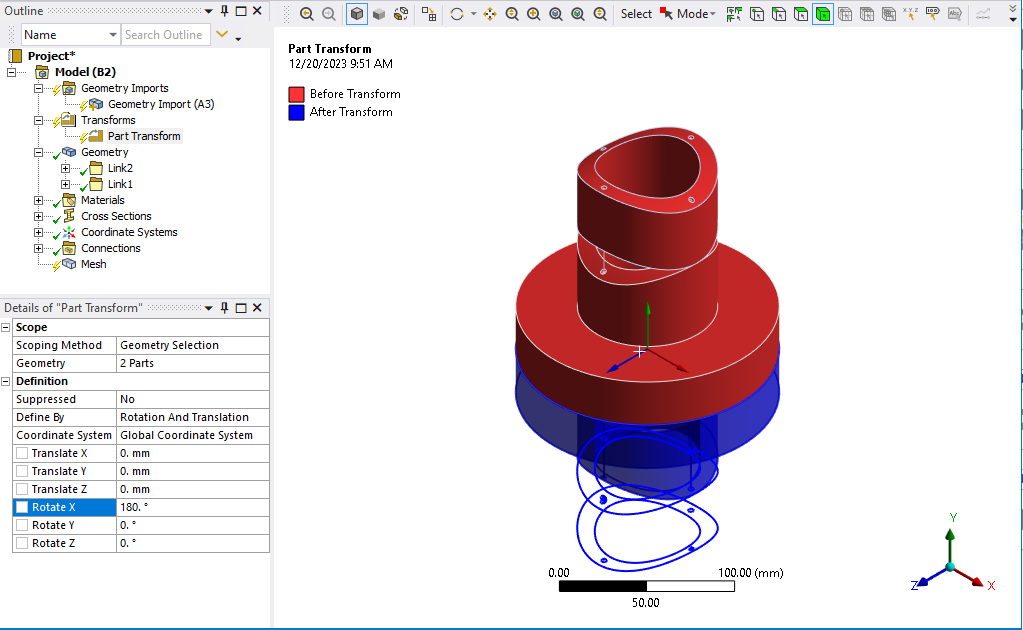
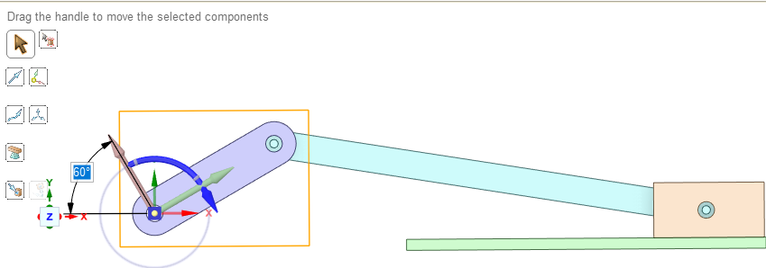
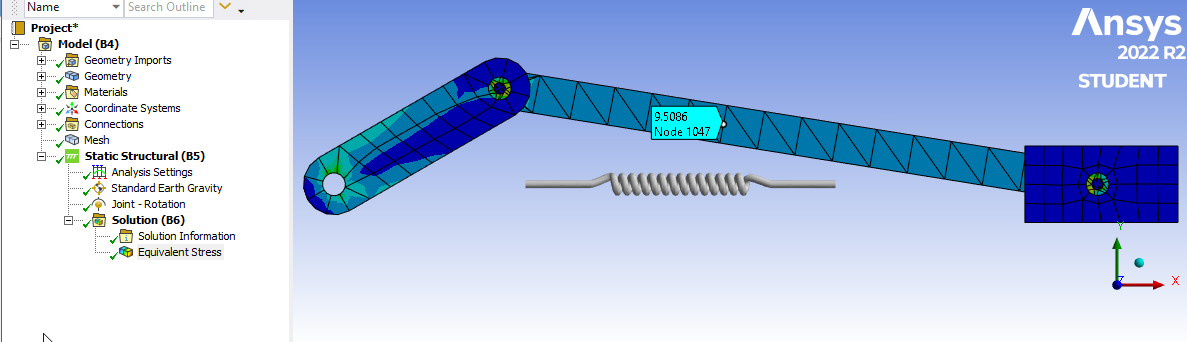
In the first attempt at building this model, the joints and spring were created using the simplest method of picking Geometry and I solved the model with the crank vertical. Then I opened SC and used the Move tool to rotate the crank by 60 degrees. Assembly constraints kept all the links properly connected in SC then I closed SC and clicked Refresh on the Model cell in WB. I was happy to find that this version of Mechanical correctly updated the joint coordinates to their new locations in space. Years ago, they were stuck at their old global coordinates. Glad to see Ansys made some progress here. I edited my comments in an earlier reply to reflect the 2022 R2 release.
Only the spring connection failed to update to the new coordinates. Notice that the Spring Length did not update so there is no additional force at this configuration and there is a gap between the end of the spring and the face. Ansys has some more work to do for a future release.
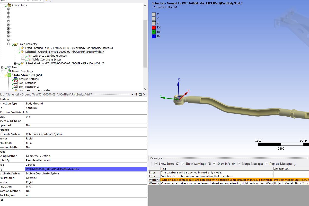
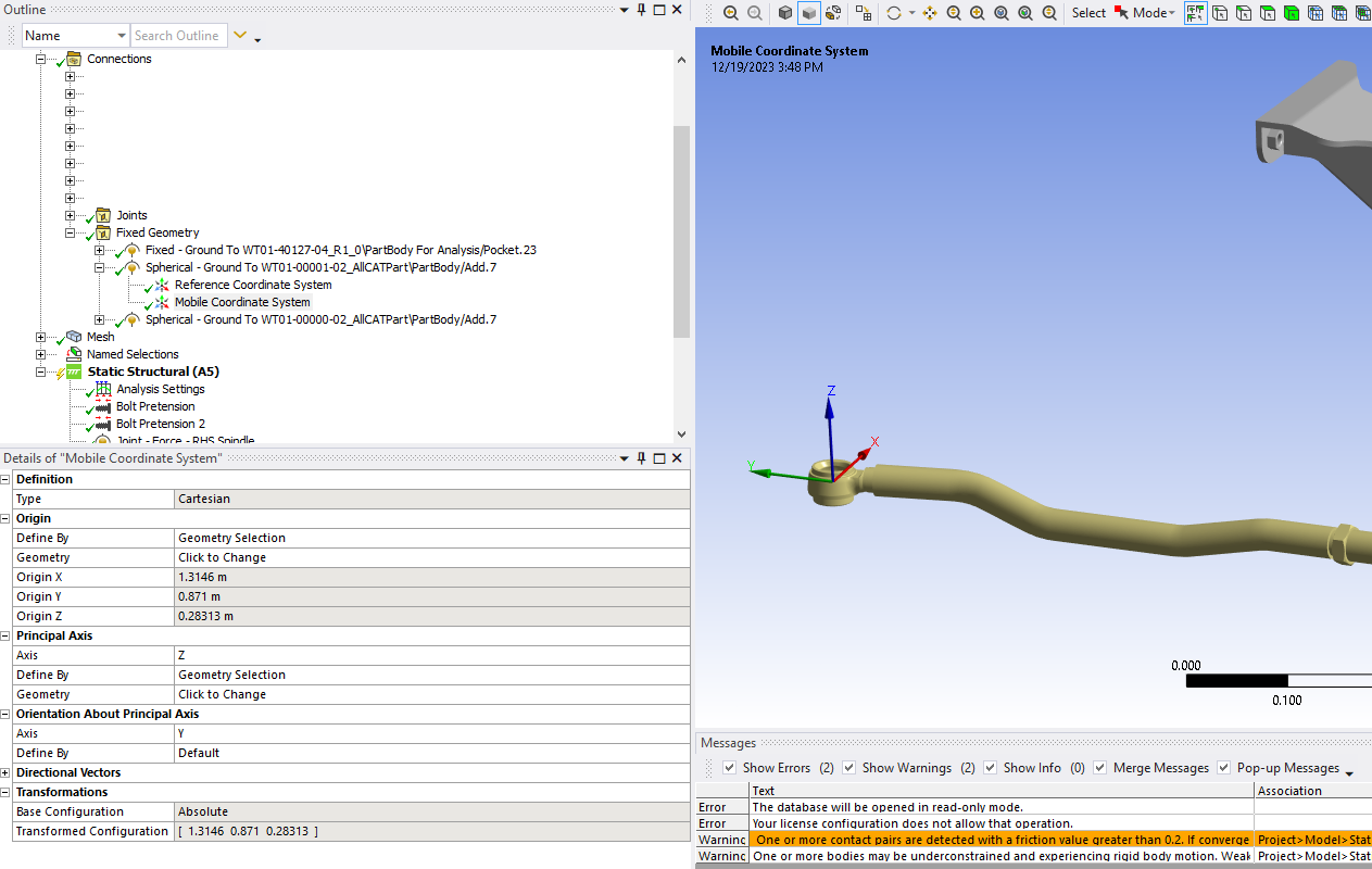
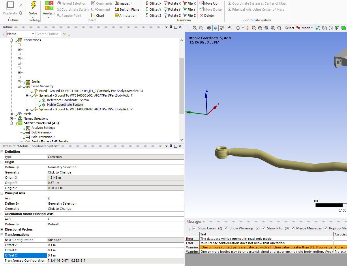
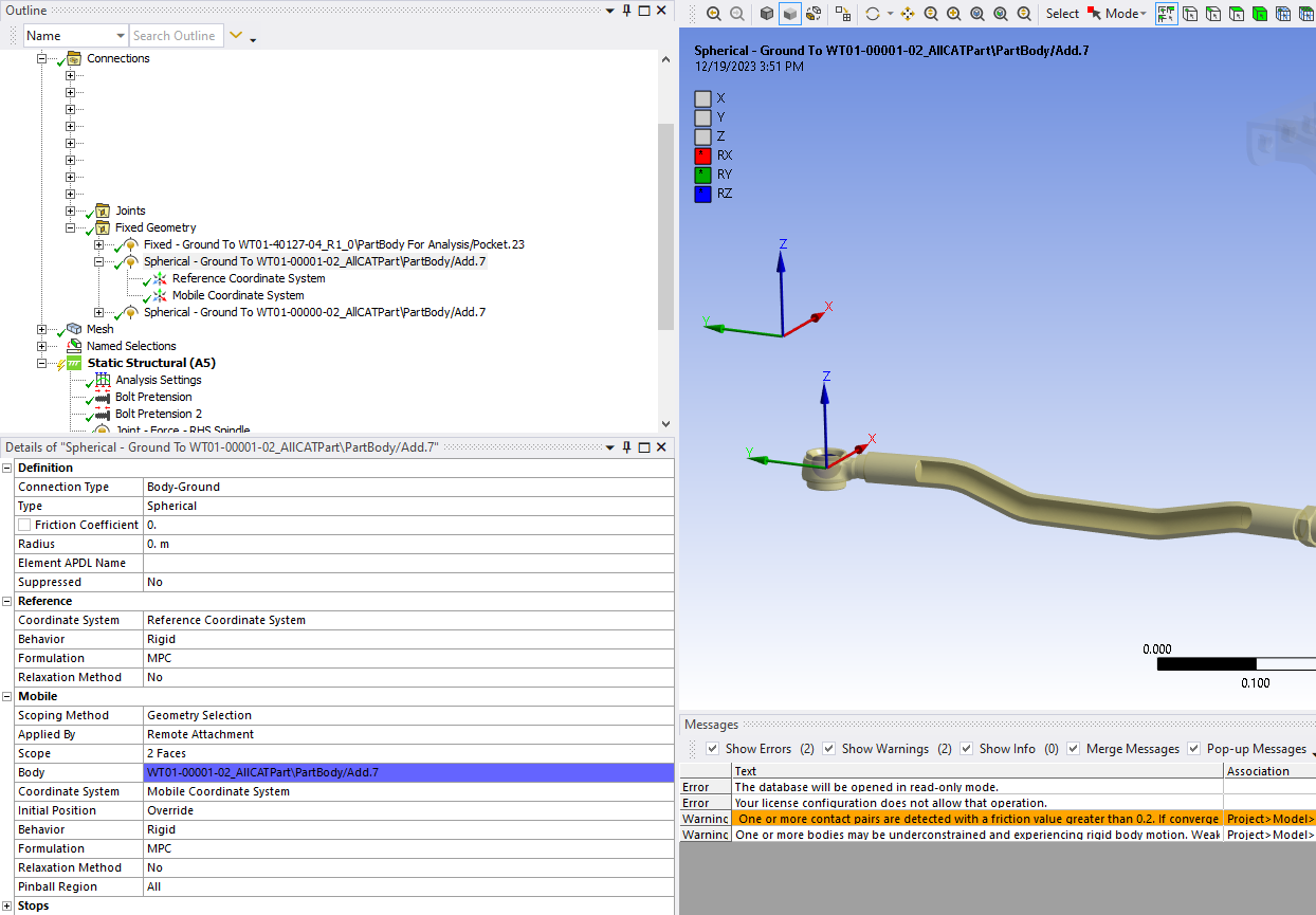
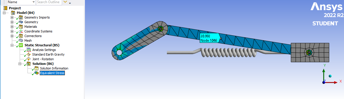
To work around this failure, I created a Local Coordinate System on that face, which will stay attached when the face moves then the Mobile end of the spring was reconfigured to use that Local Coordinate System instead of the Global Coordinate System. Notice that when the geometry updates to the 60 degree crank angle, the Spring Length correctly updates to a longer length with the same free length, so the spring force will be higher in this configuration.
You didn’t say what version of Ansys you are using. I created this example using Ansys 2022 R2 so you can open the archive at this link using that or a later version.
-
December 24, 2023 at 5:16 pm
-
December 26, 2023 at 6:15 pm
wallybanger
SubscriberHey Peter, thanks again for all the help. I hope you had a good Christmas!
OK, so we’re back to doing things in Space Claim. It’s very frusterating because both Mechanical and Space Claim have great tools but individually they are missing functionality. I have a big assembly but I don’t need to move all of the parts, just a few…. but there are no assemble to ground functions in Space Claim (as far as I can tell) so you have to fix a whole bunch of components to build the mechanism. Also, as far as I can tell, the constraints don’t allow you to select more than one surface for things like ball joints so I may not be able to make some of the constraints work. I guess you need to bring in a skeleton part to assemble things to.
In Mechanical, all of these problems would be solved by being able to define a zero point and then set the joint position. Linear movement with prismatic joints and angular movement with rotational joints. When you “configure” your joints it even pops up with the realative position so the software knows where things are, it just won’t let you define them.Anyway, it seems like this is functionality that is SORELY abscent in Ansys and it’s very basic functionality that I would consider essential for a software of this level.
I'm using 2023R1 and I see what you mean. Looking at other videos on youtube I can see the P box when using the move tool but not with this version. Frustrating.
-
December 26, 2023 at 6:55 pm
wallybanger
Subscriber||Face Palm|| I got a parameter set up for a pitman arm so I could change the orientation by modifying the angle... then, as soon as I assembled another part to it the zero reference changed and I lost the zero point. Unbelievable.
-
December 26, 2023 at 9:10 pm
peteroznewman
SubscriberHey Mike,
I did have a good Christmas, thanks. I hope you forgot about this problem for at least a day.
I have experience with several Multi-Body-Dynamics (MBD) modelers and solvers. Some years ago, Ansys had no MBD solution, then they added Rigid Dynamics, which is primitive for both modeling and solving.
The best MBD solver I have used is Recurdyn, though I found the native modeling user interface confusing.
A good MBD modeler I have used is Siemens NX/Motion which can send models to the Recurdyn solver.
Function Bay, the company that wrote Recurdyn, created MBD for Ansys, which uses the Workbench environment to build models, solve in Recurdyn and review results in Workbench. I have seen demos but have not used it myself.
Another MBD tool is MSC/ADAMS. They have a Car module for steering and suspension. I have access to MSC/ADAMS but I do very little MBD analysis so I get by with my simple models using Ansys Rigid Dynamics.
Then there are free Open Source tools for MBD. CHRONOS is specifically targeted to vehicle analysis and has suspension and steering models.
There may be a path to a successful model using Ansys where each rigid body is represented by a line between two endpoints, and joints connect the bodies. Instead of SpaceClaim, you could look at DesignModeler, which is a more primitive CAD system that allows points and lines to be defined using x,y,z coordinates in a way that SC does not. However, the way in which you want to move the end points of components around is not clear to me. If you can define a simple test case, I would be interested to see that.
Regards,
Peter -
December 27, 2023 at 7:37 pm
wallybanger
SubscriberHey Peter,
Good, I’m glad you were able to enjoy some down time. I’m in the midst of a project but I was able to put it down for a few days. I’m like a dog with a bone though so it was haunting my subconscious.
This is perhaps the only way in which Catia’s FEA functions well. Provided you don’t change the parts in an assembly too drastically you can modify assemblies very easily in regards to position and everything will update successfully, allowing you to test many different configurations without a lot of additional work.
I have a little bit of experience with NX but I have stubbornly stuck with Catia (Many times I ask myself why… the devil you know, I guess). One of the companies I subcontract for moved to NX and the people I work with have had no good things to say so far. I have worked with Solid Works, Inventor & ProE in the past. I liked ProE a lot back in the days before Wildfire and it was pretty good. I haven't used it recently though so I don't know how things have changed for the better/worse. I'm thinking Inventor might be the way to go in the future but I haven't had an oportunity to sit down and work with it in depth yet. It seems to have a large following and good support and a massive collection of interconnected tools, being part of the AutoCAD line. Good FEA support & functionality would be essential though.
I have heard of MSC/ADAMS but have never used it. I have never heard of Recurdyn or CHRONOS.It’s really unfortunate because, aside from this issue, I’m actually quite impressed with ANSYS. You can tell that a bunch of different pieces of software have been rammed together with differing levels of refinement but everything seems to work together smoothly and the solver speed is incredibly impressive compared to Catia.
Yes, that’s exactly what I was thinking about doing. I actually pulled my skeleton into Space Claim and anchored it in place but then, when I tried assembling parts to it the lines would move around and I couldn’t seem to anchor them. Perhaps I was doing something wrong. Primitive is the perfect word for Design Modeler. I’m having a hard time understanding why Design Modeler and Space Claim haven’t been merged into one program. As I said, I feel like all of the functionality is here in Ansys but it’s distributed between programs in an unhelpful manner.
Yes, for a test case what I’m working on is a double wishbone suspension. In our case I’ve redesigned the steering system in a novel manner which allows for 18″ of wheel travel with zero bump steer. That may not sound ideal but for our application it’s essential. I’m not overly concerned with testing the steering knuckle or a-arms at this point but I am testing the force inputs to the steering system in different positions… so suspension up, down, neutral and then wheels turned right, left, straight. Those photos above are the end of the tierod where they would connect to the steering arm on the knuckle.
At this point I have had some limited success by setting stops in the joints, “configuring” the joints by moving them to the extremes and hitting the “set” button. Then suppressing and unsuppressing different joints and “fix”s before running the solver. This works to an extent but does not give me fine control. It does, however, work for both the suspension and steering conditions. It is slightly more complicated because I have a component in the system where I am applying a bearing preload to a spindle using all “connections” so I need to enable revolute joints to move the steering system and then disable those joints before solving.
It appears to be working but it’s cumbersome and not as precise as I would like.
-
- The topic ‘Modifying Assembly Positioning for Multiple Cases?’ is closed to new replies.
-
6319
-
1906
-
1457
-
1308
-
1022
© 2026 Copyright ANSYS, Inc. All rights reserved.


