-
-
January 29, 2019 at 4:54 pm
liamjstrachan
SubscriberHello,
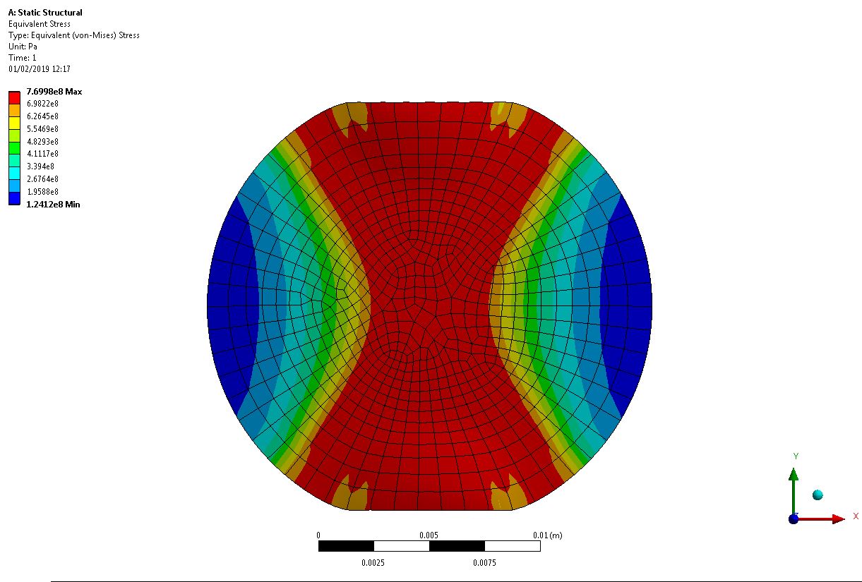
The displacement needed for yield is 1.6mm (as experimentally tested) however with mesh of 0.00065mm I get a value of 769Mpa and 384MPa (Should be 770MPa and 385MPa respectively) when using ERESX, NO command. When I reduce my mesh smaller, the solution will not converge and states to check solver output or the maximum contact stiffness is to big.
Â
As I a complete beginner at ANSYS (only been using partially for 3 months) and been stuck with this problem for at least the past 3 weeks, I am running out of solutions to produce yield.
Â
Â
-
January 29, 2019 at 6:40 pm
Sandeep Medikonda
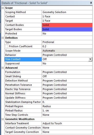
Ansys EmployeeCan you try scaling down the contact stiffness to 0.1 and also increase the pinball radius? See if it helps?
-
January 29, 2019 at 7:11 pm
peteroznewman
SubscriberLiam, please crate a Workbench Project Archive .wbpz file and attach it after you post. The file size must be < 120 MB. If it is larger, you must Clear Generated Data on the mesh, save the file and use File, Archive to make a smaller size archive. I or maybe jj77 will take a look.
-
January 29, 2019 at 8:14 pm
-
January 29, 2019 at 10:06 pm
liamjstrachan
SubscriberThanks Sandeep, will give that a shot tomorrow once I have access to ANSYS. Peter, I will also attach a .wbpz file for you to have a look at.Â
Â
-
January 29, 2019 at 10:22 pm
jj77
SubscriberI mean it is 1 Pa off, in the grand scheme that is pretty close I would say from my experience.
Â
To see if it has yielded just look on plastic strains to confirm that there are (otherwise I or Peter can have a look, me tomorrow, I am off now, it has been a hectic day, doing support and other things on 4 fronts
).
Â
Â
Â
-
January 30, 2019 at 8:50 am
liamjstrachan
Subscriber -
January 30, 2019 at 11:15 am
jj77
SubscriberNot sure if you understand fully what is happening here - NonLin FEA is not straightforward and needs time/practice and some training to understand. I would recommend a course, the are many out there (e.g., by NAFEMS)
Â
What do you mean one face shows yield, and the other 3 not, you have to be more clear than that in order for us to help you. Do you mean the tool parts upper and lower blocks (with supports). These do not have any nonlinear properties assigned to them so they are purely elastic and will never yield. Also why would you look at the tools to go into yield, normally you look on the specimen.
Â
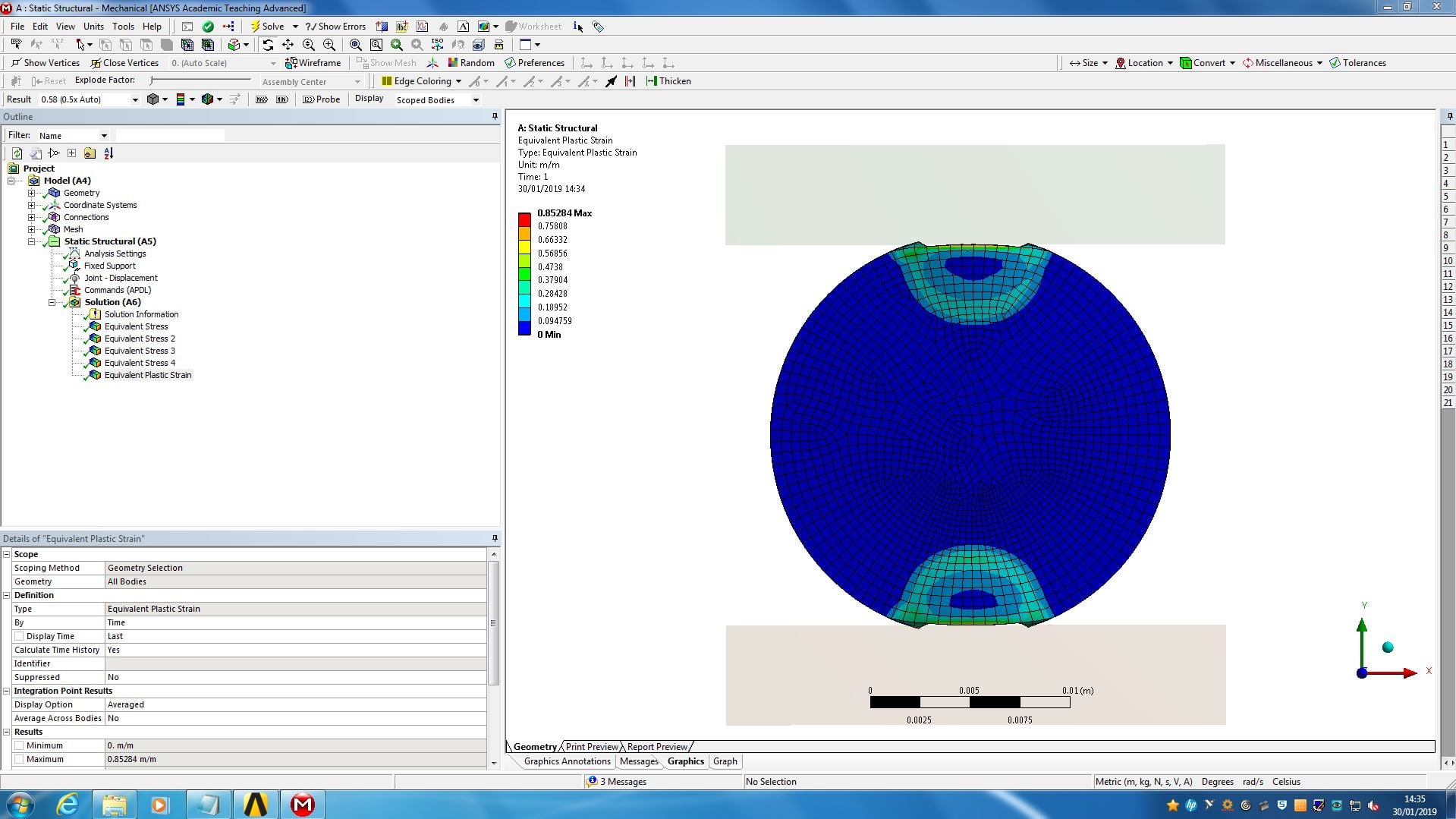
As I said to see if it has yielded you need to look on plastic strains! VM stress will not always tell you if it has yielded (as for the two upper lower blocks).
If we look at the parts shown below they have yield significantly even at a displacement of 4E-4 m. So they have yielded. The other parts as mentioned (blocks), do not show in the plastic strain because they are linearly elastic as explained . In the image you show, the part has failed (large plastic region), since one does not need any more additional force to compress it further.
Â
Hope this will explain to you what is happening.
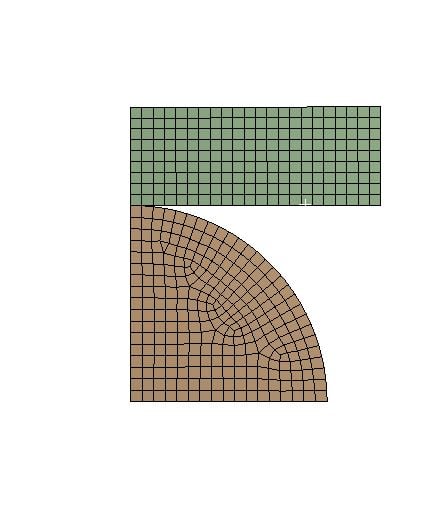
(I have a student licence hence I need to modify the model to run it, thus half symmetry and so on).
Â
-
January 30, 2019 at 1:03 pm
liamjstrachan
SubscriberApologies, I shall explain the model further.
Â
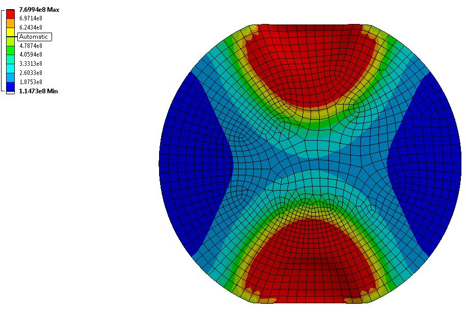
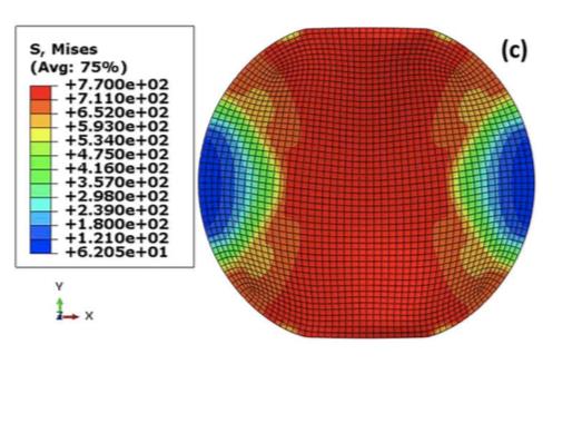
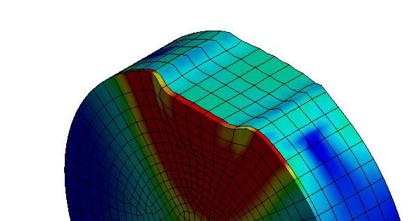
I am modelling a compression test of a substrate with a coating. When subject to a compression of 1.6mm, both materials should yield (or show failure, like the image I previously attached) as which has been experimentally tested.
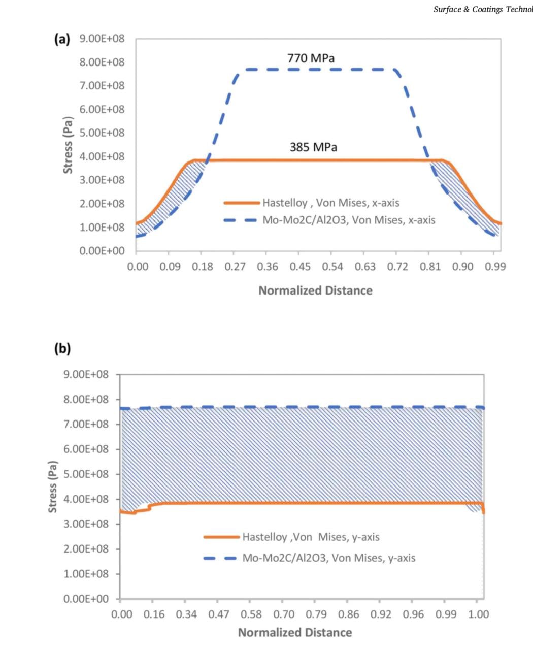
I am measuring the stress at 4 interfaces: coating, coating interface, substrate and substrate interface. Maybe so the model has yielded, however is it possible to show the failure like in the image I attached? Its only as I need to produce a mismatch in stress graph and need to measure the von miss stress at intervals on the x and y axis.Â
Â
Â
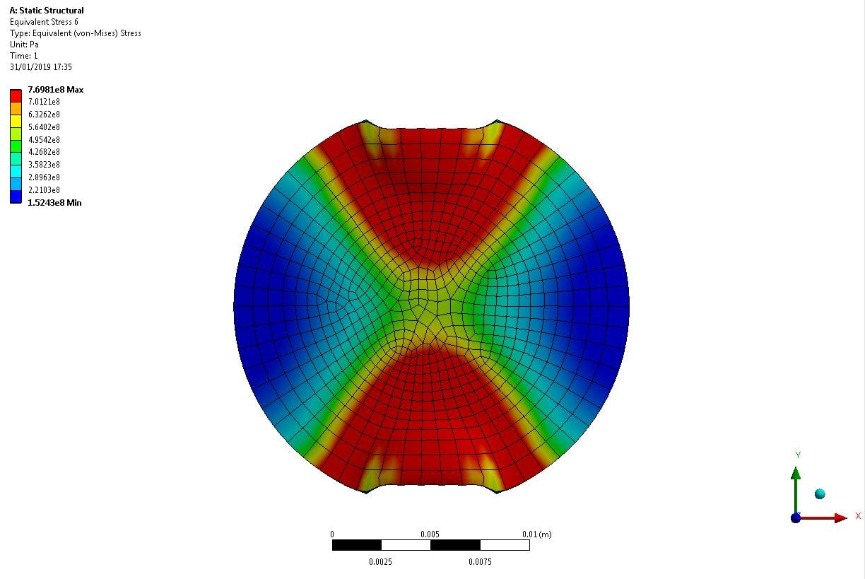
For example, the one that shows failure I can plot the above graphs, but for image below I cannot as it still shows elastic stresses in the middle of the model.
Â
-
January 30, 2019 at 1:20 pm
jj77
SubscriberOk, failure/collapse and yield are not the same. First you are saying it is not yielding, you need to distinguish between the two.
Failure (for the disc) you can see occurs when the samples/test, force vs displacement curve goes about flat as mentioned before. You can compare ansys to the experiments (and they should match).
Failure of the component (disc) is not the same as when you start to yield locally.Â
Â
Yes, you should be able to plot in ansys these graphs you need and (not sure what they show which distance and which direction).

-
January 30, 2019 at 1:40 pm
liamjstrachan
SubscriberYes, on second look my model is yielding since as the equivalent plastic strain is equal to zero which is a result.Â
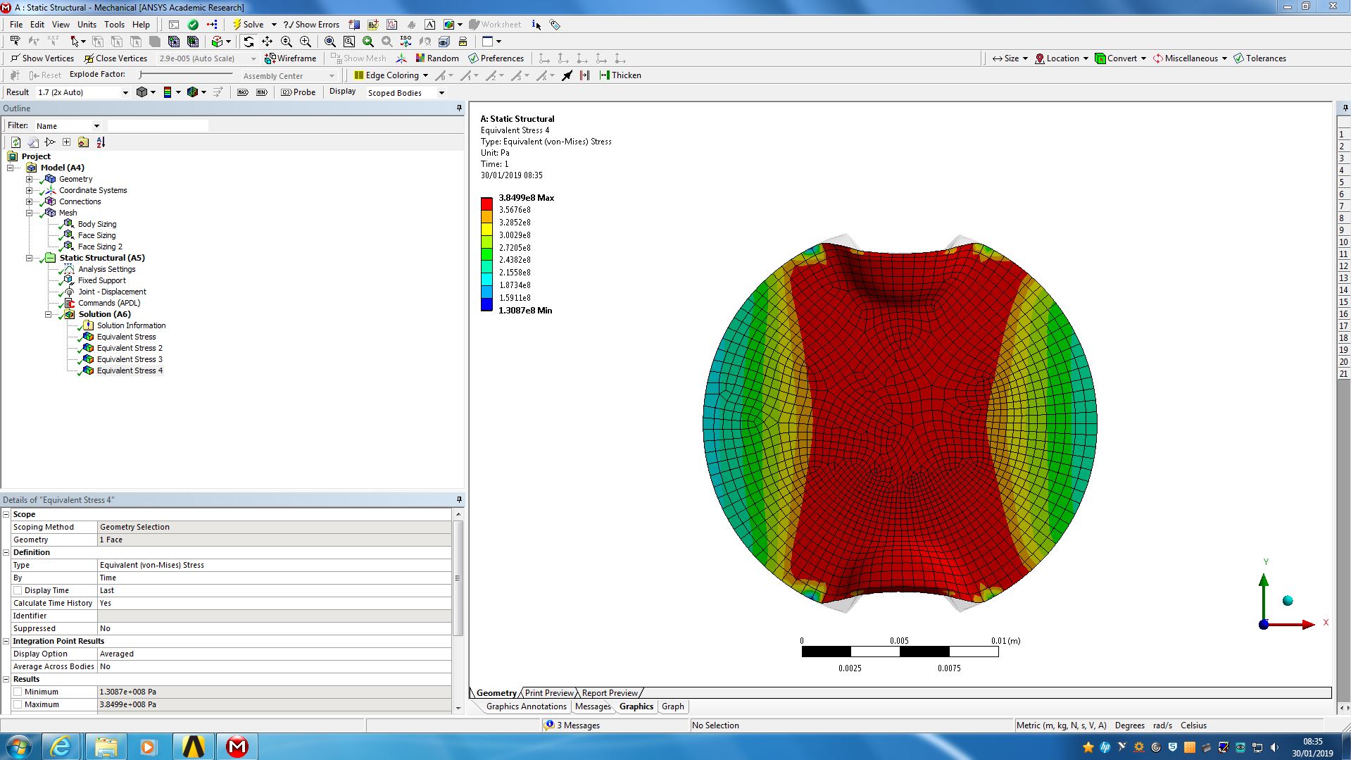
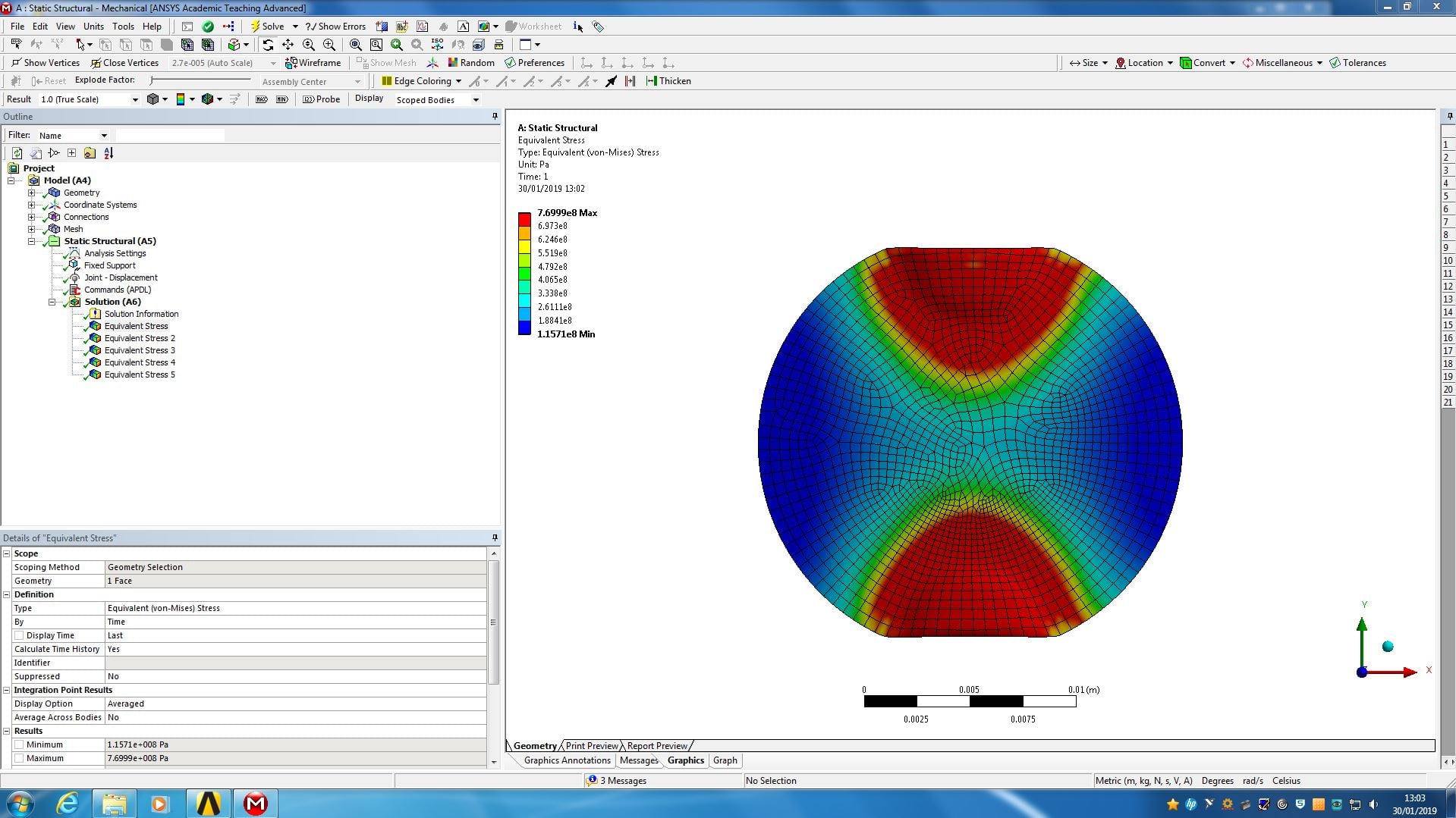
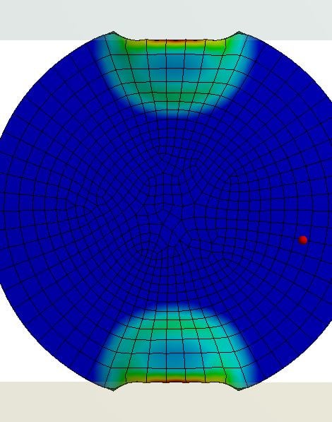
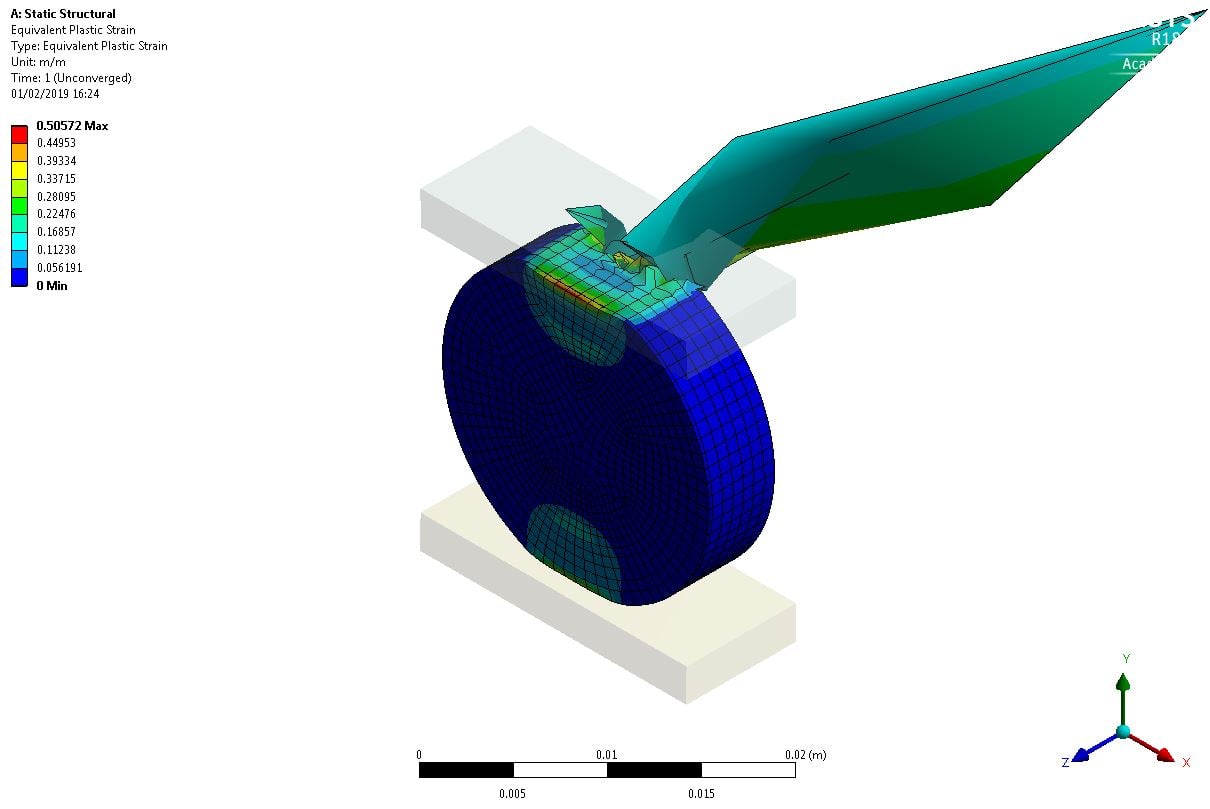
But I am confused as to why one interface is showing failure, but the other 3 are not? as they should all be showing failure with a displacement of 1.6mm, as like I mentioned, has been done experimentally. I even increased to 1.7mm and the results still did not show failure.Â
Should I further increase the displacement to try reach failure?
Pictures below show my results and what I am trying to achieve.
Â
-
January 30, 2019 at 2:25 pm
jj77
SubscriberCould you please show and image of the plastic strain for the whole disc (coat. and alloy) at your last increment (time = 1 s). Thank you.
Â
Of course to make the whole disc fail you could continue squeezing it further,
Â
Also do yo have the abaqus input file (I can have a look to see if there is a difference). Or the thesis/paper where you get this abaqus contours from.
Â
-
January 30, 2019 at 2:39 pm
-
January 30, 2019 at 2:50 pm
jj77
SubscriberOk that has definitely yielded quite a lot (looks like high plastic strains)
Bottom face would be fix Y, and left faces/sides fix X. Not sure if you see some more local "buckling" at the top, more than in the abaqus model, but I assume you might not have the same deformation scaling (should always be 1 for nonlinear analysis).
Also the edges of the contact region look a bit strange. Looks like disc is pushing itself into the block a bit.
Â
Also the width is wrong (should be 10 mm). Find out also what type of steel it is and include yield, and then do a benchmark on the uncoated part and compere FEA (load vs displacement curve) with the load curve shown in fig. 6 in that paper. That should hopefully match, and then you know that you have a model that predicts the test pretty good. From that you can then add the coating.
-
January 31, 2019 at 5:41 pm
liamjstrachan
SubscriberHello,
Â
My model has shown failure for the substrate (385MPa)Â at 1.7mm displacement, but the coating (770MPa) still wont show failure at a displacement of 2mm. When I increase my mesh size, the substrate no longer fails for some reason.
Â
Also, it looks like the compression is only happening over a small contact area since the two lips are beginning to form at either edge. Could this be a problem? as I thought only local flattening should occur.
Â
It looks like the disc is not flattening at those areas and actually inserting into the compression platen.
-
January 31, 2019 at 6:58 pm
-
February 1, 2019 at 12:44 pm
-
February 1, 2019 at 4:28 pm
-
February 1, 2019 at 10:04 pm
peteroznewman
SubscriberThat might be resolved by adjusting the time steps.
Do you have Auto Time Step set to On?
Try using Initial Substeps 100, Minimum Substeps 100 and Maximum Substeps 200
-
February 4, 2019 at 1:02 pm
-
- The topic ‘Elastic-Perfect;y Plastic Material not Yielding’ is closed to new replies.
-
6515
-
1906
-
1463
-
1309
-
1022
© 2026 Copyright ANSYS, Inc. All rights reserved.