-
-
December 31, 2018 at 12:30 am
krsowpp
SubscriberÂ
Hello there!
Recently I've stumbled upon following problem in Ansys Workbench. I'm using SpaceClaim as modeler and it seems like the tolerance of the geometry that is transfered into Mechanical is insufficient. I've proven that by comparing results from a case where the geometry is transferred from SC to Mechanical and when I export the geometry from SC to .STP file and import it in DesignModeler and then use it in Mechanical. The difference in the results are significant, up to 10% as the model is highly sensitive for insignificant geometrical changes. How do I know the problem is with transfering the geometry from SC to Mechanical and not with .STP file? Well, exported .STP file has size of about 300kb. When I import the geometry from SC in DM by using "Attach to Active CAD Geometry" and export .STP file from it, the file has the size of 11kb. Huge difference, isnt it? Again, when I import the 11kb .STP file to DM or SC and run the simulation in Mechanical, I obtain exactly the same result as I would just generate it in SC and then transfer it to Mechanical in normal way. This proves the geometry transfered from SC to Mechanical has extremely low quality in this case.Â
Is it possible to increase the accuracy/tolerance of the model that is transfered into Mechanical from SC? In Mechanical, when the geometry is transfered from SC, in the details of the geometrical entity, there is a tab "CAD Attributes", where we can find the setting called "PartTolerance" which default value is 1e-8 (0.00000001). However, the setting is grayed-out. I've spent already hours on trying to change this setting, however I found no solution. I'm desperately looking for help.
Â
Â
-
December 31, 2018 at 3:36 am
peteroznewman
SubscriberHello krsowpp,
SC and DM use different geometry kernels: SC uses ACIS and DM uses Parasolid. Those kernels use different schema for representing complex geometry. I am very interested to learn more about the differences between DM and SC. Here is one of my finds.
The file size of geometry stored in different formats is not a good indication of the amount of detail in the geometry because some file formats are in a very compact format, while others are in a verbose format. For example Parasolid uses .xmt and .xmb text or binary files to hold the same data, but the file sizes are very different.
Are you willing to share the model so I can take a closer look at it? You can attach a Workbench Project Archive .wbpz file after you post a reply by using the Attach button, as long as the file size is < 120 MB. You can make the file smaller by doing Clear Generated Data on the Model item to delete the Mesh.
There are three things to be careful of when attaching a fresh copy of geometry. (1) Some of the contacts or boundary conditions need repair and a face that was in the original model is missed, which then changes the results. (2) Another thing that can happen when a fresh copy of geometry is attached is some new contacts are automatically created but not noticed, which changes the results. (3) When fresh geometry is attached, the material that was assigned to the body in the original model is replaced by Structural Steel. Maybe you have already checked for these things, or maybe they don't apply, I just thought I would warn you about the possibility.
Some ANSYS members of the Community are very knowledgeable about geometry but you might have to wait a few days for a reply due to the holiday.
Regards,
Peter -
December 31, 2018 at 4:26 pm
krsowpp
SubscriberI am greatly thankful for your reply peteroznewman.
I have prepared the Ansys project that basically shows what is the problem I am facing. The original SC geometry is based on a script which is removed from the project. Just compare the results from the four simulations, especially maximum of the equivalent stress and the equivalent stress distribution given in the charts named "es_inner_outer". Feel free to export .STEP once again and attach them by yourself but it will not change anything.Â
-
January 1, 2019 at 3:49 am
peteroznewman
SubscriberHello krsowpp,
Thanks for preparing the Workbench archive with 4 cases. In summary,
- #1 is original geometry created in SC
- #2Â Save As STEP file from the original SpaceClaim. Import file directly into the Geometry cell of #2.
- #3 Attach Active CAD into DM from the open SC CAD
- #4 Export STEP from DM #3. Import file directly into the Geometry cell of #4.
Case #3 and #4 gives the same result as #1, but #2 gives a different result.
#1,3 and 4 were 92.3 MPa and #2 was 86.8 MPa.
It seems to indicate that the STEP file saved from SC has some lack of precision, which the STEP exported from DM does not have.
I see that under SpaceClaim Options, there are three flavors of STEP: 203, 214 and 242. I assume you used 214 which is the default. There is also an Improve Data on Export checkbox that is checked.
I see that under Tools, Options, DM has only two flavors of STEP: 203 and 214 and that 203 is the default. I wonder if that is the difference?
I tried exporting a 203 STEP file from the #1 SC file, but when I did Replace Geometry in #2 and opened the Model, it would not allow Axisymmetric to be selected under Geometry in Mechanical. The reason is one of the vertices went 1.11e-13 mm over to the -X side of the Y axis, making it invalid geometry for an Axisymmetric model.Â
Curiously, this is exactly the same value for the model in #1.
Another question comes to mind: if you do a mesh refinement study on Model #1, how much does the pressure move around? I also notice that NLGEOM is OFF. If I turn that ON and use a much more refined mesh, the pressure on #1 becomes 89.8 MPa.
Regards,
Peter -
January 1, 2019 at 7:15 pm
krsowpp
SubscriberThank you again peteroznewman. According to your mesage I tried exporting the original SC model to .STEP v203 and v242 and DM model to v214. All of them worked for me, I didn't experience the problem you mentioned with the axisymmertic simulation type, despite X coordinate of the vertex was negative. I obtained following results:
SC export: v203: 86.8 MPa, v214: 86.8 MPa , v242: 86.8 MPa.
DM export: v203: 92.2 MPa, v214: 92.2 MPa.
The results show that the version of .STEP doesn't matter. Mesh refinement resulted in negligible changes of the peak stress value. Integerestingly, turning on NLGEOM changed the results to the following values:
SC export:Â 86.8 MPa -> 85.9 MPa
DM export: 92.2 MPa ->89.8 MPa
Turning on NLGEOM is a simulation detail (quite important) but that does not affect the accuracy of the geometry.Â
 You wrote: "It seems to indicate that the STEP file saved from SC has some lack of precision, which the STEP exported from DM does not have."
I think the lack of precision occurs in all the other cases and that the .STEP file exported from SC is simply more (sufficiently) accurate. Lets take a look how the .STEP files are defined in both cases. Reading the files in notepad we can see that the surfaces in.STEP files are defined by 4 edges, two straight segments (x=0, y=0) and two B-splines:
#71=EDGE_CURVE('',#77,#78,#79,.T.);
#72=EDGE_CURVE('',#78,#80,#81,.T.);
#73=EDGE_CURVE('',#80,#82,#83,.T.);
#74=EDGE_CURVE('',#82,#77,#84,.F.);
#75=FILL_AREA_STYLE('',(#85));
#76=FILL_AREA_STYLE_COLOUR('',#86);
#77=VERTEX_POINT('',#87);
#78=VERTEX_POINT('',#88);
#79=LINE('',#89,#90);
#80=VERTEX_POINT('',#91);
#81=B_SPLINE_CURVE_WITH_KNOTS(<<<set of coordinates>>>)
#82=VERTEX_POINT('',#1950);
#83=LINE('',#1951,#1952);
#84=B_SPLINE_CURVE_WITH_KNOTS(<<<set of coordinates>>>)
Â
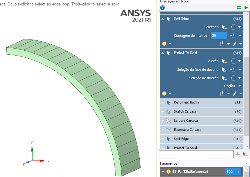
In case of the .STEP file exported from DM B-Splines are based on 20 coordinates (points), which is extremely insufficient. While the geometry is exported from SC to .STEP file B-Splines are based on 1857 coordinates. I am positive this is the issue in my analysis, therefore my initial question was how to increse the accuracy of the geometry exported directly from SC to Mechanical (not to .STEP file).Â
-
January 1, 2019 at 10:30 pm
peteroznewman
SubscriberHello krsowpp,
Now you have explained it in terms of the number of points on the B-Spline in the STEP files, I see that it is case #2 that has the higher precision, and all the others lack this precision due to a lack of spline points sent from either SC or DM to Mechanical. Now I fully understand, thank you.
The point of mesh refinement and NLGEOM was to compare the magnitude of the geometry difference with other factors.
I see now your concern that the data sent from either SC or DM to Mechanical is, for this geometry, insufficiently precise, and the full precision can only be obtained if the STEP file is directly read to Mechanical. This is a good defect for the ANSYS developers to correct. I don't work for ANSYS, but am interested in making sure the software is as precise as possible.
I came up with a workaround that returns the precision of the exported STEP file found in #2, to the direct SC-to-Mechanical interface, without exporting a STEP file to get that. I have labeled it #5 in the attached archive. It involves creating an array of 88 lines at 1 degree increments that are projected onto the surface. This results in a pressure result of 86.8 MPa, the same result as #2. This is further proof that an insufficient number of points on the spline are being sent to Mechanical from SpaceClaim.
I hope one of the ANSYS employees will submit this as a defect. Let me know as I can submit this through SimuTech if necessary.
Regards,
Peter -
January 2, 2019 at 12:13 am
krsowpp
SubscriberDear Peter,
That basically solves my problem. I will just improve the method of the geometry division with a little script. I really appreciate your time and knowledge, you helped me a lot! I hope Ansys will refer to the problem. Now I can proceed with my research.
With best regards,
krsowpp
Â
 -
November 11, 2022 at 1:45 pm
Heitor Facuri Cicoti
SubscriberHello, Peter and krsowpp.
This discussion was spot on for my problem. Thanks for that!
But there aren't any files attached, so I'm not sure what the solution was exactly, and how I could implement it in my case.
The STEP export/import does improve the precision indeed. Unfortunately I need the direct SC to Mechanical link, because I'm running 1175 design points with parametrized geometry.
I'm running a 3D simulation on a quarter of an oval ring, created with an ellipse line in the sketch. So, in my case, an array of 88 surfaces intersecting the part would be the solution? Or maybe create the array of lines before extruding (pulling)?Â
Thanks in advance!
-
November 11, 2022 at 7:07 pm
Heitor Facuri Cicoti
SubscriberI managed to solve it by splitting the external face into 20 faces (even 10 seems to be enough for my case).
Just use Split, select Split Edge, select the circumference edge, and input the Counter for the number of divisions wanted.
Then, using Project, select every other split edge and, on Select Target Faces, select the face to be splitted.
Â
-
- The topic ‘CAD models from SpaceClaim – insfufficient tolerance of geometries.’ is closed to new replies.
-
6104
-
1906
-
1436
-
1308
-
1021
© 2026 Copyright ANSYS, Inc. All rights reserved.


