
-
-
December 29, 2018 at 9:07 pm
jackhero
SubscriberI intend to model the non-linear behavior of reinforced concrete in ANSYS workbench. I have seen some discussions and videos regarding this and have some confusion and problems which I would like to clarify. From the experimental results I had the load-displacement values which I later converted to flexural stress and flexural strain. According to the discussion (Multilinear Kinematic Plasticity created from a stress-strain graph), the engineering stress and engineering strain should be converted to true stress and true strain before entering the values for a material in Engineering Data. I followed the calculation in that discussion but I am getting the both Engineering stress-strain and True stress-strain curves almost similar. I also checked the plastic strain with and without offsetting, plotted with true stress but still had some issue, had almost the same curve.

Another discussion (Non-Linear Analysis_Multilinear Theory), the user input the values of Raw true stresses and True plastic strains for multi-linear theory (Multi-linear isotropic hardening MISO). Can someone please comment on the calculations are correct or not? Also, as mentioned here that should not have the negative slope on the True Stress vs Plastic Strain curve in a multilinear plasticity material model. How can I correct it for my case?
I assume that for entering material non-linearity and inputing the values of experimental results we only need to input the true-stress and plastic strain values. From hereafter, I will be referring these two as stress-strain only. If there have some exception, specially related to concrete, then please correct me. Also some researchers have only mentioned the stress-strain values were input, but they didn't mention whether be engineering or true stress strain or plastic strain with true stress. From what I have searched so far I think it is understood to use the plastic strain with true stress as an input.
Some of the articles I read have used MISO for entering the stress-strain curve or values for the material used along with SOLID65. However, some have mentioned the usage of Drucker-Prager or Menetrey-Willam models for the input of stress-strain values for concrete. I would like to ask if I only input the MISO will it be enough to define the non-linear behavior instead of defining the Drucker-Prager or Menetrey-Willam models. In addition, these models require compression and tension results which I do not have and also I am trying to simulate the bending only.
In Abaqus, I read some articles only defined concrete damage plasticity and didn't need to physically design the reinforcements and successfully ran the simulation. In Ansys workbench, as an alternate, I suppose we have the Drucker and Willam model. Could this also be done by defining the MISO only?
I intend to model the cracking as well in my static structural model. SOLID65 element is famous for showing the cracking in simulation. However, experts have suggested in some discussion using the SOLID18X elements. Are the SOLID18X able to have the cracking behavior as well? So far what I have searched I think they can not simulate the cracking behavior. If not, then is there any workaround in workbench for modeling the cracking or I shall use SOLID65 only?
Also, in some articles, they have skipped the ANSYS models instead have used the Multilinear elasticity (MELAS) to simulate the non-linear concrete. How can I define the Multilinear elasticity (MELAS) in workbench?
-
December 30, 2018 at 12:31 am
peteroznewman
SubscriberHello Jack,
I will add a few comments that will address some of your questions. Perhaps others will provide further information.
Multilinear Kinematic Plasticity is ideal for ductile metals. Below is an image of the uniaxial test data in Engineering Stress and Strain.

You can only use Engineering Stress-Strain data from a Uniaxial Tensile Test up to the point when necking begins at the Ultimate Stress. After that, a key assumption is violated and the equations that convert Engineering Stress-Strain to True Stress-Strain are invalid.

The True Stress - True Strain curve keeps increasing after necking, but you can't use the Engineering Stress-Engineering Strain to obtain the curve. What you can do is guess what it might be and run a model with that guess. The model will simulate necking and create a Force - Displacement curve. Obtain the error between the Force - Displacement curve from the experiment and the simulation to inform a revised guess for the True Stress - True Strain curve. Iterate until the two curves have better agreement in the post-necking portion of the curve.
Concrete cracks and crushes as it fails, so its Force - Displacement curve has jumps in it, unlike ductile metals.
The combination of the CONCRETE material model and the SOLID65 element allows the element to keep track of the cracking and crushing. However, it is well known that this combination is extremely sensitive to the mesh. In other words, you can plot a Force - Displacement curve for one mesh, then when the mesh changes or is refined, you get a significantly different Force - Displacement curve. That is a problem for getting agreement with experimental data.
The mesh sensitivity of the CONCRETE/SOLID65 combination was one of the motivations for moving to the Microplane model that tracks the softening behavior of the concrete as it fails, without having to track individual cracks. The microplane model with a newer CPT215 element delivered Force - Displacement results that had no significant mesh sensitivity, and agreed very well with the experimental data. A Technology Guide shows how to use the Microplane model with the CPT215 element.
Regards,
Peter -
December 30, 2018 at 1:59 pm
Mirghani
SubscriberHello Jack,
I am also interested in the non-linear behavior of concrete and the different concrete models available. As far as I know, up to date there is no other way in ansys to physically see the concrete cracks beside using the SOLID65 element (legacy Element). As stated by Mr. Peter, now ANSYS provides a model that efficiently simulates the gradual failure of concrete "the micro-plane model" with a newer CPT215 element. in addition to the technology guide and the previous discussions in this forum the only example I could find about micro-plane in ANSYS is available in YouTube (maybe you saw it already-in Russian language). They are comparing the results of the old method using SOLID65 with the new micro-plane model with current technology elements I didn't have the time to rebuild it my self though. maybe some one in the community will have the time to create it.
Youtube link: https://www.youtube.com/watch?v=Vb-xVXdY3Go&t=5s
-
December 30, 2018 at 8:47 pmSubscriber
Thank you Peter and Mirghani for your reply and for the video.
For the Microplane model,
1. Do I only need to input the parameters shown in the image below (taken from the Technology Guide file which you shared in your reply) ? Although the table doesn't mention the input of stress-strain curve(or points), but for confirmation do I have to input the stress-strain points or only the parameters are enough when using the microplane model for concrete? Also in the video the user only mentioned the parameters not the stress-strain input values in microplane model.

2. I searched for the input parameters for microplane model and found the following,
Link 2 (I found this file in one of the discussion, but forgot the link so uploading it here)
But, the parameters mentioned in these two links are same as those given in the video but different than the image which I uploaded from the Technology Guide. I am not sure where I am mistaking, but could you please comment on the difference of these two inputs and which input parameters should I follow?

3. How can I calculate the input parameters of microplane model for modeling concrete from my bending experimental results?
4. The microplane is valid with the SOLID18X elements as well. I have seen references using microplane with SOLID18X along with discrete reinforcement using REINF. I would like to confirm does microplane if used with SOLID18X will support the smeared reinforcement REINF as well? For my model, the reinforcements will be fibers only and for which i think smeared be more suitable.
5. How will the reinforcements whether be discrete or smeared (if supported), effect the microplane output in concrete bending simulation? As for some of the Abaqus models I have seen they only input the concrete damage plasticity (no reinforcements) and the simulation matches well with the experimental results of reinforced concrete. -
December 30, 2018 at 9:56 pmSubscriber
Jack,
Link 1 above is obsolete and members are discouraged from linking to sharcnet, you can get information for 19.2 at this link
https://ansyshelp.ansys.com/account/secured?returnurl=/Views/Secured/corp/v192/ans_mat/microplane.html
If you are delivered to the Customer Portal instead of the page, here are the instructions for getting to that page.
To get the files for the Technology Demo, use the ANSYS Help system to go to this page:
https://ansyshelp.ansys.com/account/secured?returnurl=/Views/Secured/corp/v192/ans_tec/tecintro.html
On that page, scroll to the end and you will find td-54, where you can download the files that are used to run the reinforced concrete microplane model.

With those files, the guide and some experimentation, you should be able to answer many of your questions yourself. I don't have the answers.
You might also look at the ten references provided in the ANSYS Help for the Material Reference section on Microplane.
https://ansyshelp.ansys.com/account/secured?returnurl=/Views/Secured/corp/v192/ans_mat/microplane.html%23matmicroplanereadlist
Regards,
Peter -
December 31, 2018 at 8:22 pmSubscriber
The True Stress - True Strain curve keeps increasing after necking, but you can't use the Engineering Stress-Engineering Strain to obtain the curve. What you can do is guess what it might be and run a model with that guess. The model will simulate necking and create a Force - Displacement curve. Obtain the error between the Force - Displacement curve from the experiment and the simulation to inform a revised guess for the True Stress - True Strain curve. Iterate until the two curves have better agreement in the post-necking portion of the curve.
By guess, do you mean something like shown in figure with red, yellow and blue (colored) curves to match the required curve (shown in black). The input points are marked roughly with green dots on the curves. Keeping in mind that the input entry for MISO do not support negative slope so I have not included any decrease in the stress values of the colored curves. I shall to run the simulation with all of the colored curves one by one (or maybe more) until I get the required/desired result to match the black one.

-
December 31, 2018 at 11:46 pmSubscriber
Jack,
MISO is good for ductile metals. I don't know that it is suitable for concrete. For example, a tensile test of a metal sample will exhibit necking, while a tensile test of a concrete sample will not exhibit necking.
If you have a ductile metal, you can guess a True Stress vs True Strain curve, create a simulation of the Uniaxial Tensile Test, and generate a Force-Displacement curve, then compare that with experimental data from a Uniaxial Tensile Test and update the guess for the curve. I don't know if you can take experimental data from a bending test and compare that with simulation data from a bending model. The MISO data is based on Uniaxial Tensile Tests, so I don't know if making corrections to those curves from bending tests is going to work out.
Regards,
Peter -
February 11, 2019 at 12:47 pm
FlaviaGelatti
SubscriberHi, Mirghani
I ordered a translation of this video, it is not going to be in english, but then I can pass on what they are explaining.
If I can offer some hep about Microplane model:
There are 2 ways of inputing the model, as the Release Notes explane for the Version 19:
"The microplane material model is now available in two forms: an elastic microplane model with damage, and a new coupled damage-plasticity microplane model."
- The Elastic Microplane model with damage is supported by the element Solid185. A snippet example
ET,MATID,185
MP,EX,MATID,29100
MP,NUXY,MATID,0.2
TB,MPLANE,MATID,,6
tbdata,1,0.75,0.75,0.208,6.109e-05,0.512,98 !k0,k1,k2,α_mic, β_mic, beta_mic
- The Coupled Damage-plasticity Microplane model is supported by the element CPT215. This model was presented on the paper by Zreid and Kaliske (2014, 2016, 2018)
(link to the 2018 paper: https://dl.acm.org/citation.cfm?id=3296167)
A snippet example
ET,1,215
KEYO,1,18,2
MP,EX,1,29200
MP,NUXY,1,0.2
TB,MPLA,1,,,DPC !Define Drucker-Prager
TBDATA,1,25.5,26,2.044,1,4e4,-40 !fuc,fbc,fut,Rt,D,sigVc
TBDATA,7,2,0,2e-6,1500,750 !R,gamt0,gamc0,betat,betac
TB,MPLA,1,,,NLOCAL
TBDATA,1,1500,2.5
-
February 11, 2019 at 6:04 pmSubscriberHi flavia
Thank you for explaining the two different command snippets for the microplane model and the link. Am still following the old fashion way when modeling concrete. I tend to use The legacy SOLID65 element with concrete material model specially when I have a relatively small model and also due to its cracking and crushing capabilities. However I think microplane model is favorable when it comes to larger models due to it's accuracy and less mesh sensitivity issues. I will definitely give it another try as I tried it before although it doesn't support cracking and crushing of concrete.
PS: waiting for your feedback regarding the video.
Thanks -
February 16, 2019 at 10:51 amSubscriber
If the model is small, and there is not much nonlinearity involved, the Solid65 is a good option to view the cracking. Although to view the cracking you have to apply the load in one step, and that affects the results... so is a reference problem.
But if your structure is strongly nonlinear, the Microplane model is much more robust. I would suggest to use Solid65 model to understand the behaviour in a general sense (and view where the cracking and crushing occurs) and then move to a Microplane model to extract results.
I encourage you to try again, and if I can help, please let me know.
P.S.: The translation should be ready by next week, I'll keep you posted.
-
February 17, 2019 at 2:04 am
sujitbhandari
SubscriberHi Jack,
I am also working on nonlinear analysis of Concrete-like (Masonry) structure. I have used Microplane model with coupled damage-plasticity. It is much more robust than using Concrete model of SOLID65. As members above have explained, SOLID65 doesn't give good results in nonlinear range. Another model I have came across and have got good results is use of Geomechanics nonlinear material properties; I have used Drucker-Prager Concrete model. I am not sure if it's available in Engineering Data in WB. But, you can always insert some code snippets. I have attached the link. However, I would have to warn you that I have run into problems with HSD behavior. I can't sort that till now, when I turn on HSD behavior.
Have a look. Maybe this model will suit it.
Regards,
-
February 17, 2019 at 3:22 amSubscriber
Hi Jack,
About Microplane model: I have read a lot about the model, like a lot, in the past month. MP model is best in terms of convergence, and solve time (that's I've found). I think you can't just define MP from stress-strain curve. You have to define the parameters. To define the parameters, maybe this slide on elastic microplane might help:
If you are to use the damage-plasticity model (I guess that is best suited for NL analysis with damage, and cyclic loading), then you should have seen the Material reference in ANSYS. The section towards the last gives you some tips on getting the parameters. (You will need data from cyclic load testing, and that might be somewhat difficult, I guess!). Here's an article on nonlocal parameters, I guess, this will be of help.
-
February 17, 2019 at 1:33 pmSubscriber
Thank you for the references @sujitbhandari. The Drucker Prager model is also available in Engineering Data in workbench.

@Sujitbhandari @FlaviaGelatti
Any suggestion based you may provide on your knowledge for microplane would be helpful.
I designed the symmetry model for three point bending of concrete for non-linear behavior using the microplane model. Experimentally I have the bending test result which I intend to verify using FEA. I calculated the microplane parameters, as was mentioned in the help section by using the tensile test experimental result and calculated some of the parameters via equations. The unknown parameters I kept same as are mentioned in (A gradient enhanced plasticity---damage microplane model for concrete). The boundary conditions are as following;

Top load is -0.5mm in y direction and all other components and rotations were zero. Whereas, the bottom support have zero in y-component and free for other components and rotations.
The resulted stress values are too low as shown below;

I also tried altering other parameters and changing the applied boundary conditions value but the results are almost same. Most of the times the resulting image was not homogeneous, the image was somewhat similar to what @FlaviaGelatti has shown in his post here. Although the resultant values are normal in @FlaviaGelatti attached pdf model but for my case the resultant values are too low and also had the unordinary image of the beam at the end of the simulation. I applied remote displacement as the load on the top whereas i think in @FlaviaGelatti model remote force was applied as a load on top.
I entered the microplane parameters as following ;
ET,MATID,215
KEYO,MATID,18,2
MP,EX,MATID,25000 ! Define Elasticity Modulus (enter a value for E)
MP,NUXY,MATID,0.2 ! Define Poisson's ratio
TB,MPLA,1,,,DPC !Define Drucker-Prager
TBDATA,1,31.368,36.074,3,1,7e4,-24.049 !fuc,fbc,fut,Rt,D,sigVc
TBDATA,7,2,0,2e-5,5.5e3,3e3 !R,gamt0,gamc0,betat,betac
TB,MPLA,1,,,NLOCAL
TBDATA,1,1600,2
I followed the discussion Remote Displacement - Beam model between @jj77 and @FlaviaGelatti. Although they sort out the issue at the end, but I still can not figure out the problem in my case.
-
February 17, 2019 at 2:13 pmSubscriber
Just looking at your code, I think you have made a error in defining MP. I guess, it should be TB,MPLA,MATID,,,DPC and so on. You may want to correct that and have a go. I guess, you are defining the MP model for material 1, which I don't think is what you intended. I am also working on microplane right now, and am not getting the results as expected. Getting the right parameters for your model can be quite tricky, I guess. But, the following papers might have something useful. Have a go:
Jiang, H., J. Zhao. "Calibration of the Continuous Surface Cap Model for Concrete." Finite Elements in Analysis and Design. 97 (2015)
Zreid, I., M. Kaliske. "An Implicit Gradient Formulation for Microplane Drucker-Prager Plasticity." International Journal of Plasticity
But, I am finding it very hard to define parameters for microplane, I have to admit, especially for masonry when you haven't got much data on cyclic loading.
That's all I could help for now. Best wishes,
-
February 18, 2019 at 1:43 amSubscriber
Hi all,
Again about microplane: Do anyone of you happen to know the source of the formulas used in the Russian video about microplane? It would be of great help to get to know how these parameters are calculated.
Cheers,
-
April 21, 2019 at 2:17 pmSubscriber
Cheers everyone
I finally translated the russian video and I'll post what I consider most important to our topic. I ignored some of the parts because I belive most of you already know or it can be seen in the video itself.
I apologize in advance for any misspelling and welcome any contributions/corrections.
There are two constitutive models analyzed, the Willam and Warnke (W-W) model and the Microplane model. The W-W is used with the Solid65 elements, and the Microplane is used with Solid185 elements. All the commands that control de Material Definition, Solution and Output where defined by APDL codes, as can be seen on the video. The author modeled a simple reinforced concrete beam, nothing important to comment on this.
1) Solid65 Model
There are some recommendations on the Solid65 model that are interesting.
- Mesh: The external nodes (corner nodes) of the hex elements must superimpose the nodes of the beam elements (used to model the steel reinforcement). This guarantee that the deformations of steel and concrete are compatible.


(Node aligment of solid65 elements and Beam188 / Solid65 element with no midside nodes)
This is necessary because the solid65 element is not created with midside nodes, and its internal behavior is linear, while the default mesh is quadratic. So you have to define the Mesh as Linear so the elements are compatible with the Solid65 topology, and the model don’t get distorted when the results are shown.
- Solution Control: Here we have the APDL commands to controls Solid65 model solution. Most of these commands you guys probably know, and they are easy to find in the online documentation.
NLGEOM,OFF
SOLCONTROL,ON,OFF,NOPL
NROPT,UNSYM !Here we set the Newton-Raphson as unsymmetric option. This option is good to help convergence, because the cracking create matrix asymmetry.
PRED,OFF,,OFF
LNSRCH,OFF
NEQIT,100
KBC,0
cutcontrol,plslimit,0.2
cutcontrol,cutbackfactor,0.25
cutcontrol,noshape,1
SHPP,WARN
pirchek,off
- Equation Solver Control: These are the APDL commands to solve the system equation.
EQSLV,SPARSE,1.0E-8,3.0,,
BCSOPTION,,INCORE,16000,,,OFF
- Output Control and Convergence criteria: There commands define de number of substeps and the convergence control. There are 2 load steps, so there are 2 APDL commands – one for each load step. It is also important in the window Details of each APDL go in Step Selection Mode and chose “by Number”, and then in Step Number “1” for load step 1 and “2” for load step 2.
Load Step 1:
AUTOTS,ON
NSUBST,3,100,3,OFF
time,25.0
outres,all,all
STABILIZE,OFF,,,,
CNVTOL,F,2.0E-9,0.5,2,

Load Step 2:
AUTOTS,ON
NSUBST,20,1000,20,OFF
time,35.0
outres,all,all
STABILIZE,OFF,,,,
CNVTOL,F,,0.5,2,1.0E-3
- Crack View: The APDL commands to view the crack pattern can be easily seen in the video. So here I’ll just transcript the important part. You can view the crack pattern in any load step, not just in the first one. But for you to be able the chose the load step you HAVE to define the different load steps by APDL (not just by the Workbench options) and define each APDL command to each load step in the Details window (see the above procedure). How to chose a load step to show the crack is on the following APDL commands:
*SET,step_number,2 !Chose the load step 2
*SET,substep_number,5 !Chose the substep 5 of the load step 2
SET,step_number,substep_number,,,,,
PLCRACK,0,0
The rest of the APDL commands of the crack view is to adjust de zoom etc and to create a loop to generate one view for each substep. Not necessary.
- Final considerations: He recommends, to improve convergence, to use element key option (3) as value 2. And key option (7) as 1, and this means that the Solid65 element constant C9 will used (the default value is 0.6). Just to be clear: KEYOPT (7) controls the stress relaxation after cracking (so the stiffness don’t drop to 0 right after crack).
2) Microplane Model
Most of the commands are the same. I’ll focus on what is different.
- Material model: Now the material model changed from Willam-Warnke to Microplane. So before we had “tb,concr,MAT_ID,1,,1” and now is “tb,mplane,MAT_ID,1,6”
- Finite Element: the elemento type now has changed, we use Solid185.
- Mesh: Microplane support quadratic behavior of elements, this means that in Mesh you can use the quadratic option in Element Order. This one of the best advantages of Microplane model.

- Solution Control: Now we use full Newton-Raphson. Before we had “nropt,unsym” and now we have “nropt,full”. This is because the Microplane model is a Damage Model with matrix symmetry, and the failure is considered in a much more elegante way than the abrupt way of WW in Solid65.
Now the great difference comes in use of the constitutive model. A great difficulty in the use of the Microplane model comes from the fact that its parameters does not correspond directly to any mechanical characteristic or material resistance. They are numerical parameters of a numerical model.
It’s convenient to remember that the Mplane is coupled with a Isotropic Damage Model [1], so some of the parameters are necessary to define what is called a Damage Function – a function responsible for representation of the damage on the material (i.e. cracking). The 3 parameters are γ, α and β, and they define when the damage begin, how it will evolve and how much damage the material can stand.
As for the rest of the parameters, it’s also convenient to know that the Damage Function must be written in terms of Equivalent Strain, which is a function of the Invariants of the Strain Tensor (I1 and J2), and this Equivalent Strain is a scalar measure that controls de damage. There are many ways to define this E.S., but here is used the modified Von Mises definition:

This Isotropic Damage Model does not take into account the different behavior of concrete under tension and compression. So the K0, K1 and K2 parameters are the result of the adaptation of the model to the different response of the material under tension and compression [2]. k is a model parameter that sets the ratio between the uniaxial compressive strength fc and uniaxial tensile strength ft.
After all these brief comments, it’s interesting to note that the experimental data are important to define the input data of the Microplane model. Four experimental data of the concrete correspond to four point in a graph, the surface created is the limit of the elastic domain, beyond this limit we have a damage in the material. The trick is to correspond the experimental data with the graph domain.

- Microplane parameters values: There are 6 parameters to be defined. The 3 parameters related to the Equivalent Strain can be calculated using experimental data as input values (see the video and the Excel worksheet). The other 3 parameters are related to the Damage Function, and they must be adjusted according with each problem.
Now, you can define the k0, k1 and k2 with simple equations:

But they will provide slightly different values for the parameters. They can be used if you don’t have all the experimental data.
- Viewing the damage: Although with Microplane/Solid185 you can’t see the cracking and crushing of the material, you can insert a User Defined Result under the Solution branch. The Expression must the Damage Criteria:

And it should look like this:

So you can see the elements that suffer with an Equivalent Strain greater than the γ (Critical Equivalent strain energy), or the value that correspond to the beginning of damage.
Note that there are 3 User Defined Result, one for the First Invariant I1, one for the Second Deviatoric Invariant J2 and one for the failure criteria itself (see figure above).
References for the theory:
[1] – HOFSTETTER and MESCHKE. NUMERICAL MODELING OF CONCRETE CRACKING. 2011
[2] - Groot et al. Failure stress criteria for composite resin. 1987
I hope this can help
Regards
Flávia
-
April 21, 2019 at 2:24 pmSubscriber
Link to the excel worksheet:
https://www.dropbox.com/s/7pmwt1cb01ih5i0/Microplane%20parameters%20calculation.xlsx?dl=0
-
April 25, 2019 at 5:20 pm
-
April 26, 2019 at 12:19 pm
Yato
SubscriberI did a small study to obtain the microplane parameters. In case someone helps:

-
May 6, 2019 at 9:23 pm
antonyony
SubscriberFlavia,
Is there a way to view the damage using APDL language?
-
May 7, 2019 at 12:00 pmSubscriber
Hi, Antony
I don't think so.
The damage shown in the picture of the beam (the not visible elements ) is a result of a failure criteria defined on the WB interface by the User. I tried to export the APDL file of the structure (Tools > Write Input File) to check if Ansys would transcript the criteria to APDL language, but he ignores it.
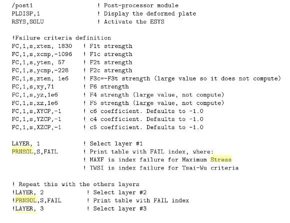
I didn't explore it, but maybe you can try the coding below. It uses a FAIL criteria and you can write in APDL. This print is from the book Finite Element Analysis of Composite Materials Using ANSYS® by Ever J. Barbero
-
May 7, 2019 at 1:40 pmSubscriber
Flavia,
I'll check it out, thanks.
Are you Flavia Gelatti from Itajai University?
I'm having a hard time modeling concrete, I'm thinking of just using the linear microplane model, as the full scale tests of my composite beam didn't show any form of cracking.
-
May 7, 2019 at 4:01 pmSubscriber
Yes, I work at Itajaí University.
What kind of composite beam are you trying to model?
Maybe you could start with Willam-Warnke model (solid65 element) to understand more of its behaviour and post here the results.
-
May 7, 2019 at 4:45 pmSubscriber
I'm Brazilian too.
In my research I work with the stub-girder floor system, first presented by Colaco, then extensively studied by Ritchie and Chien.
I've tried using solid65 but I had difficulties concerning convergence. I was not able to obtain a load-displacement curve with this method. When the cracking started the convergence problems got worse.
I'll post the results here as soon as I'm finished.
Thanks!
-
May 29, 2019 at 11:22 am
m.gryniewicz
SubscriberHello everyone. FlaviaGelatti - You have done a great job. I am impressed with your willingness to help. I know some Russian language and I can help if something could be still confusing. I tried to translate this video too.
Unfortunately, I still trying to solve this VL1502 example as they have done. But I still have a problem with SOLID65 case. I am using research Ansys 19.2 and I am not sure that there something changed from the later versions? I do not know where I have a mistake.
When I use BEAM188 I get the convergence problem at a second substep of the first step and my deformations look like this:
When I use LINK180 everything seems to be ok but I have only linear deformations and different ones than those in the video.
Did anyone do the version with SOLID65+BEAM188 with success?
-
May 31, 2019 at 1:58 pmSubscriber
Hi, Marcin
I never saw a model with Solid65+Beam188. I belive the use of Link180 for the reinforcement is more interesting because there is no rotational DOF.
On the matter of the deformations: did you insert the APDL with the BISO model for the LINK180 element?
Btw, I'm using 19.2 version. If you post the file of the model here we can work on it together.
-
May 31, 2019 at 4:15 pmSubscriber
Hi FlaviaGelatti,
Thank You for Your answer. I have a problem with LINK180 too.
I know using LINK180 is more reliable but I wanted to see what with happen when I use beam like element. Just for curiosity, appartof the fact that this kind of element was used in this video.
I will check my project to find if I used the BISO model. Now I have no access to PC with Ansys.
Please find my model under the link below:
https://www.dropbox.com/s/96js5xa3u9v6wxs/concrete2.zip?dl=0
Thank You in advance.
-
June 4, 2019 at 6:57 pmSubscriber
My mistake, Marcin... I have the 19.0 version, so I can't open the file. My apologies.
But I'm modeling the VL1502. As soon as I have a stable model, I'll post here.
-
June 7, 2019 at 3:47 pmSubscriber
Hello,
OK, I understand

Here You can find listings from main commands. Maybe would appear to be helpful:
-
June 13, 2019 at 12:04 pmSubscriber
Hi
There is no way my model with Beam188 can converge. I checked and our commands are the same.
The result of the solver looks like this, and It looks to me that both elements (solid65 and Beam188) are not working together when the nonllinearity begins. I don't know if that is the result you are getting... But if I were to guess, I think we should be using the Table Points to define the nonlinear behavior of the concrete (concrete 2 APDL of the tutortial).

I created the model with solid185 and link180 to, and the results are much more stable.
-
June 13, 2019 at 6:13 pmSubscriber
I tried running the model with the nonlinear behavior of the concrete, entering the data points for the constitutive model shown in "Material Model (concrete 2)" APDL.
I had a better result with the nonlinear response of the beam. The file can be found bellow:
https://www.dropbox.com/s/4ylw0ieu5tbfm3u/VL1502.wbpz?dl=0
-
September 24, 2019 at 12:17 am
Diegoandree1311
SubscriberI am having problems with the modeling of a flat plate slab in Ansys WB, I am trying to model the hognestad A1 slab, but LINK180 steel is not having contact with solid concrete 185. This is my thesis and I have been trying to learn for almost half a year my account reading Ansys manuals but I think it's time to ask for help
these are the concrete commands, then steel, and the preprocessing commands respective
!Data Element Type
ET,1,SOLID185
!Data Material Properties
MP,EX,1,30640
MP,NUXY,1,0.2
!Data Input Non Metal Plasticity-Concrete
TB,MPLAN,1,1,6
TBDATA,1,0.784,0.784,0.123,5.33e-5,0.7,30
!Data Input Stress-Strain Non Linear - Multilinier Kinematic Hardening (Model Kent-Park Unconfined)
TB,KINH,1,1,7
TBPT,DEFI,0.0001,3.064
TBPT,DEFI,0.0005,13.886
TBPT,DEFI,0.001,24.194
TBPT,DEFI,0.0015,30.922
TBPT,DEFI,0.002,34.072
TBPT,DEFI,0.00219,34.33
TBPT,DEFI,0.003,29.181
This is the link180 reinforcing steel
ET,3,LINK180
MP,EX,3,199947.96
MP,NUXY,3,0.3
TB,BISO,3,1,2
TBDATA,1,414,50000
SECTYPE,3,LINK,ELASTIC,BARRAinf,0,
SECDATA,286.51
ELIST,,,,,1
/ESHAPE
preprocessing commands
/PREP7
ESEL,S,ENAME,,185
ESEL,A,ENAME,,180
ALLSEL,BELOW,ELEM
CPINTF,ALL,0.00001,
ALLSEL,ALL
/SOLU
OUTRES,ALL,ALL
I am interested in learning to use more commands that help me with this purpose, as is the case of the REINF mentioned by colleague Wenlong, but I don't know how to put it into my programming
I really want to learn to use Ansys but it is a world, and as the thesis I have to deliver it in 4 months, I have no time to lose, thank you very much to all who can help me beforehand, greetings

-
September 24, 2019 at 9:20 amSubscriber
Hi.
I think its better for you to start a new discussion in order to get more attention.
you can follow the below links it might be helpful
how to contact rebar (Link180) to (SOLID65) concrete element Here
follow wenlong answer at the end of this discussion Here
you can search through ansys student community, there are many helpful posts & answers regarding reinforced concrete
Good luck
-
October 20, 2019 at 11:58 pm
zoiralli
SubscriberHello everyone,
I am trying to work solid65 command for unreinforced UHPC. I have followed the suggestions above, but my results are not right. The commands which give more accurate results are the following:
*SET,ELEM_TYPE_ID,1
ET,ELEM_TYPE_ID,solid65
KEYOPT,ELEM_TYPE_ID,1,0
KEYOPT,ELEM_TYPE_ID,3,2
KEYOPT,ELEM_TYPE_ID,5,0
KEYOPT,ELEM_TYPE_ID,6,0
KEYOPT,ELEM_TYPE_ID,7,1
KEYOPT,ELEM_TYPE_ID,8,0
and for concrete model:
ET,MATID,SOLID65
R,MATID,0,0,0,0,0,0
RMORE,0,0,0,0,0
MP,EX,MATID,48000
MP,PRXY,MATID,0.18
MPTEMP,MATID,0
TB,CONCR,MATID,1,9
TBTEMP,22
TBDATA,1,0.2,0.8,15,120
TB,MISO,MATID,1,3,0
TBTEMP,22
TBPT,,0.0035,120
TBPT,,0.0025,108
TBPT,,0.0015,72
My main problem is how to input the stress relaxation factor (c9) as the TBDATA command allows only 6 constants. In the manual it is stated that: "If constants 1-4 are input and constants 5-8 are omitted, the latter constants default as discussed", meaning C9 should be 0.6 which is the default value. However, when I edit the model in APDL C9 is set to zero. What should I do to include in the command the C9=0.6? Thank you in advance.
Regards,
Zoi
-
October 21, 2019 at 12:03 amSubscriber
@Zoi,
Please copy your post above and open a New Discussion.
Use a link to reference this discussion.
-
October 27, 2019 at 9:46 pmSubscriber
Hello guys,
I created a new discussion about the problem I am having to model post-cracking behavior of ultra high performance concrete. If someone could help me, please go to /forum/forums/topic/non-convergence-due-to-material-failure-or-problematic-contacts-please-help/
I would really appreciate any help!!
Thank you in advance,
Zoi
-
May 2, 2020 at 1:46 am
israelcrawford
SubscriberCan i get help with modelling a linear reinforced concrete model ?
-

- The topic ‘Entering non-linearity in Workbench for concrete’ is closed to new replies.


-
peteroznewman
 6575
6575 -
scabo
 1906
1906 -
Dennis Chen
 1463
1463 -
javat33489
 1311
1311 -
Shyam Prasad V Atri
1022


© 2026 Copyright ANSYS, Inc. All rights reserved.
