Ansys Assistant will be unavailable on the Learning Forum starting January 30. An upgraded version is coming soon. We apologize for any inconvenience and appreciate your patience. Stay tuned for updates.
General Mechanical

General Mechanical

Topics related to Mechanical Enterprise, Motion, Additive Print and more.

Beam connection / fixed joint

    • VigneshKC
      Subscriber

      Hi all,


      Presently I am working on structural analysis of Humanoid Robot and I would like to ask for some suggestions/tips. 


      I have found the loads acting on the ankle joint of the robot from a dynamic simulation and I would like to find out the stresses acting on the member. I have Applied the Forces and Moments acting  at one joint but I am not sure what boundary condition to apply for the other. 


      I initially though to apply a fixed joint but then I was suggested to apply a beam connection. I am not sure which one to use. Could anybody suggest me with a solution or some references to solve my issue. Attaching a screen shot for better understanding.


      Thanks,


      Vignesh

    • peteroznewman
      Subscriber

      Hi Vignesh,


      In future posts, please use the Insert Image button on the reply toolbar to show the image inline with the text because ANSYS employees are not allowed to download attachments.  Here is your image from above:


      Each end looks like a bearing or shaft fits in those holes.


      The force B seems to have a component that would rotate the part around end A.


      What physical feature on the top, prevents rotation about the axis of the holes? 


      Regards,
      Peter

    • VigneshKC
      Subscriber

      Hi Peter,


      I will make sure to use the insert image button in my future posts. 


      The force A and the moment B are the o/p of a dynamic simulation. The force and moment are obtained by placing a force sensor at the lower joint during the simulation as shown below.


      My understanding was these are the forces and torques felt by that particular link while performing the task. 


      So the upper joint can be considered like a motorized joint which provides a resisting torque. (On thinking Yesterday I realized that fixing the lower joint and applying a equal and opposite force will represent this situation better)


      Hope I was able to give you a better picture.


      Thanks and Regards,


      Vignesh

    • peteroznewman
      Subscriber

      Hi Vignesh,


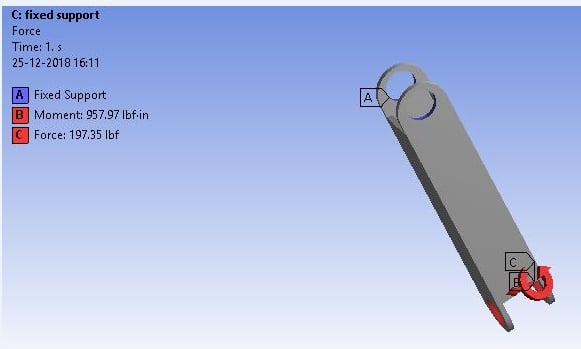
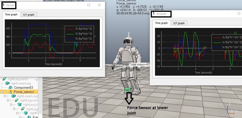
      In a simulation, a lot of detail from the real world can be left out. In the Dynamic model, you can define a motorized joint through the axis of the two holes at end A and another motorized joint through the axis of the two holes at end B and get output data on the force and torque. I understand that.


      Now you want to know the stress in the part due to that force and torque. This is where the real world detail needs to be considered. The motorized shaft that is coupled to end A has features that clamp it to those two holes and those features are not in the model.


      If the maximum stress occurred some distance away from the two holes at end A, then you would be fine to use fixed support on the ID of the two holes. The problem is that it looks like the maximum stress will be in the material around the two holes at end A, so if you just fix those faces, you will introduce an error compared with having the detail of how the shaft actually couples to the two flanges of end A. 


      Regards,
      Peter

    • VigneshKC
      Subscriber

      Hi Peter,


      Wishing you a Happy New Year.


      Thanks for your reply . I think I will go with fixed joint at the support A (the solutions of beam and fixed support are not very different) . The error that you mentioned, unfortunately I can't do anything about that at this stage of the project since we are in the conceptual design phase only. When we get into the detailed design phase I will definitely keep your suggestion in mind.


      Thanks and Regards,


      Vignesh

    • peteroznewman
      Subscriber

      Thank you Vignesh.


      I have used a few different software packages for MBD. What software are you using?


      Regards,
      Peter

    • VigneshKC
      Subscriber

      Hi Peter,


      I have tried a few software packages myself for MBD simulations. Presently I am working on V-REP . 


      http://www.coppeliarobotics.com/


      Thanks and Regards,


      Vignesh 

Viewing 6 reply threads
  • The topic ‘Beam connection / fixed joint’ is closed to new replies.
[bingo_chatbox]