-
-
November 22, 2023 at 8:53 am
Hien Doan
SubscriberHello,
I am running the simulation of the simple cylindrical cavity which is splitted into two halves in z-axis.
I want to check how to quality factor changes if there is a gap between two halves.
However, I don't know how to build a model in HFSS that can simulate the gap of the cavity.
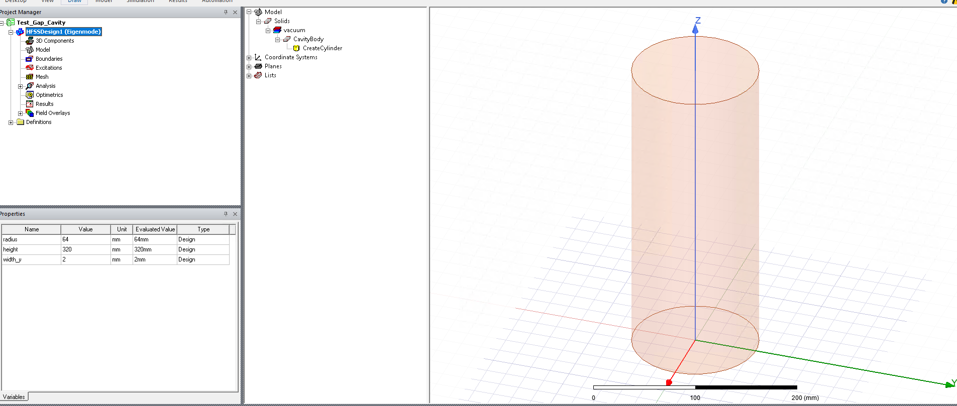
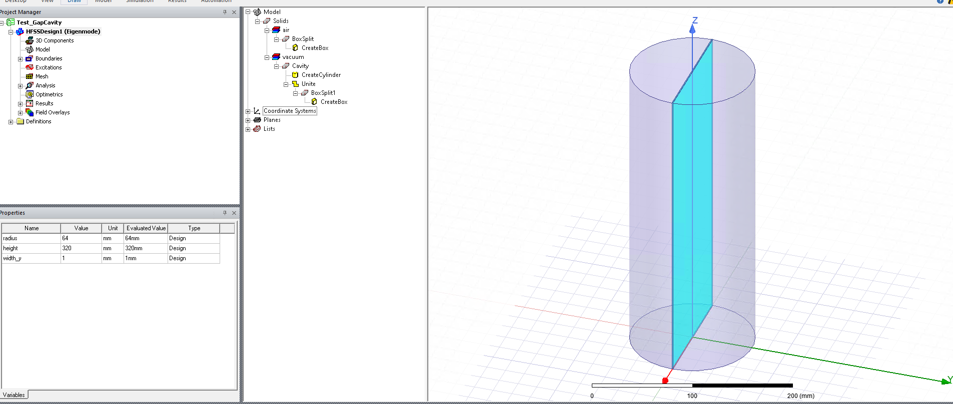
What I tried is: draw a cylinder cavity, and the very thin box with dimensions: x-width = 2*cavity_radius, y-width=1mm, z-width=cavity_height
Then I subtract the box from the cavity, set finite conductivity for the cavity and assign material 'air' for the box.
However, it doesn't seem to work because the quality factor is higher than the orginal cavity (which is not subtract for the box).
Could anyone tell me how to solve the problem, please?
Many thanks and best regards,
Hien.
-
November 28, 2023 at 1:57 am
dushyant.marathe
Ansys EmployeeHi Hien,
Thanks for posting your query on Ansys Learning Forum.
I could understand that you are trying to simulate cylindrical cavity splitted into two halves alog z-axis and probably to create a split you are subtracting the thin box.
However, I would like to know which solution type in HFSS you are using for cavity simulation to get quality factor.
I would also request you to provide screen shots of splitted cavity, cavity before split and subtract operation from HFSS model tree.
Thank you.
-
December 7, 2023 at 9:53 am
-
December 18, 2023 at 6:52 am
Hien Doan
SubscriberHi Dmarathe,
Could you please help me to check the model?
Thanks a lot!
-
December 19, 2023 at 5:00 am
dushyant.marathe
Ansys EmployeeHi Hien,
There was some delay from my side to get back to you. I have looked at screenshot that you attached here. It is very difficult for me to identify the issue just from the screenshot. Therefore, I am suggesting you a better approach,
Complete Cavity: You can create a cylindrical cavity and assign finite conductivity boundary as you did earlier. I would suggest that being a cylindrical object, go to ‘initial mesh setting’ dialog and check ‘Apply curvilinear meshing to all curved surfaces. You may try plotting mesh on your cavity just to check that it is sufficiently dense.
Spitted Cavity: Create a cylindrical cavity, use a ‘Split’ option from ‘Draw’ tab to split the cavity into two halves along desired plane say ZX. Use move operation to move one of the cavities to create a desired gap. Now assign finite conductivity boundary. Make sure that you check ‘Apply curvilinear meshing to all curved surfaces.
Please verify results again.
Thanks,
-
December 28, 2023 at 3:23 am
Hien Doan
SubscriberDear Dmarathe,
Thanks for your reply.
Actually, I had tried using 'Split' option from 'Draw' tab as you mentioned.
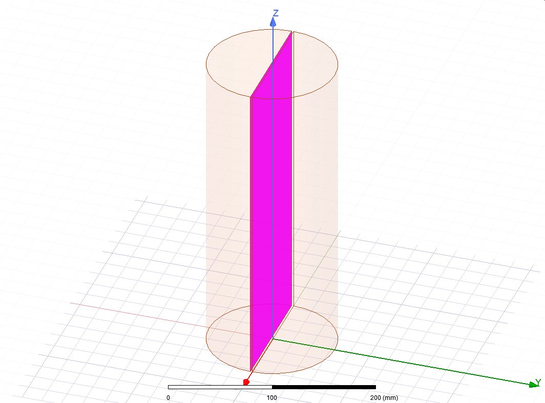
However, after Splitting and move one of half cavity to create a gap, these two halves become independently cavivies as you can see in the figure below.
And what I want is one cavity with a gap between two halves.
Do you have any idea how to remove the surfaces (as shown in pink in the plot above)?
Many thanks for your help!
Best regards,
Hien.
-
January 25, 2024 at 4:50 am
dushyant.marathe
Ansys EmployeeHi Hien,
You can create a splitted cavities as I suggested earlier to create a separation/gap. This gap you need to fill either by using Box (Draw Box) of same size as gap or use Line feature to Draw the Lines connecting the vertices between two cavities on either end and then form a close surface/sheet. You will have to create four such faces to close the gap.
If you have access to Ansys Technical Support, please raise a service request and our support engineer will get in touch with you and clarify all the doubts.
Thanks.
-
- The topic ‘Simulation cavity having a gap with HFSS’ is closed to new replies.


-
5014
-
1683
-
1387
-
1248
-
1021

© 2026 Copyright ANSYS, Inc. All rights reserved.


