-
-
November 29, 2018 at 3:35 pm
shaheen wahab
SubscriberHello,
I have been trying to mesh the channel with a pile at the center, but I am not satisfied with the mesh that is being produced. I have used several Sphere of Influence with 0.2 m element size and an “Automatic method”. The average size of the elements is between 0.3 - 0.5 m. I have also used 2 inflation layers (one around the pile and the other from the bottom surface) and merge them. The mesh gives me some weird looking elements on the side walls (image attached). The number of nodes and elements is quite high (1133359 and 5038577 respectively). The skewness of the elements is found to be 0.71 [Good] although I had changed the target skewness to 0.70 and the orthogonal quality is found to be 0.19 [Acceptable]. I have attached images of the mesh and if you have any suggestions to make it better, it would be really great!
Thank you
With regards
-
November 29, 2018 at 4:55 pm
Rob
Forum ModeratorI think that's an extruded 2d case? If so, and it's for CFD can you model as 2d?
Otherwise, read up on the sweep method and use that. You probably need to remove most of the sizing before you do that and pick some more sensible global sizes. The odd mesh in the first image is because the quality criterion are met with one or two cells in that gap, or two or three cells: changing to sweep will also resolve that problem.
-
November 30, 2018 at 6:10 am
Keyur Kanade
Ansys EmployeeAs Rob said, you can create hex mesh using sweep method.
Also for tet mesh, I see the mesh is ok at the center. The mesh on the sides is also ok. If you want to refine the mesh on sides, please use body sizing.
https://caeai.com/resources/tips-tricks-hex-brick-meshing-ansys-e-learning
-
November 30, 2018 at 9:22 am
shaheen wahab
SubscriberThank you, Rob, I will try the way you suggested.
-
November 30, 2018 at 9:24 am
shaheen wahab
SubscriberThank you Keyur, I will try it.
-
November 30, 2018 at 3:30 pm
shaheen wahab
SubscriberDear Rob,
I have tried several times and unfortunately, I couldn't get a good mesh. I tried doing the sweep method. The geometry has two bodies divided horizontally, so I used two methods. Is there any way to have something like "inflation layers" near the bottom? Also, what could be done to have smaller elements near to the pile?
Yes, it's a 2D extruded case. I first made the geometry in YZ Plane and then extruded in the X direction for 200 m. In that geometry, I then made the pile and then extruded it. I don't understand exactly when you said to do it in 2D? Did you mean that I make the geometry first in 2D with the pole and then extrude it in Z direction for 2 m (which is the depth of the channel)?
I would be very grateful if you could help me in this regard.
Thank you
With regards
Shaheen
-
November 30, 2018 at 4:30 pm
Rob
Forum ModeratorI mentioned a 2d model as unless you need to see the effects at the top & bottom of the extruded section (YZ planes) you don't need to model the thickness.
What is the purpose of the simulation: it's easier to advise when we know the desired outcome of the model.
-
December 2, 2018 at 12:40 am
peteroznewman
SubscriberShaheen,
I think I can demonstrate a good quality mesh by sweeping up from the bottom. There may be some geometry prep to make this happen. Please attach a .wbpz file and let me try.
Regards,
Peter -
December 4, 2018 at 4:17 am
Keyur Kanade
Ansys EmployeeYou may want to use edge sizing for prism effect while using sweep method.
Make sure that sweep direction edges have same node count.
https://www.youtube.com/watch?v=D8UzdC5Gmhs
-
December 5, 2018 at 10:58 am
shaheen wahab
SubscriberDear Peter,
Sorry for replying late as I was stuck in some other task related to my Thesis results and I didn't read the message. Yes, I am attaching the .wbpz file.
I have attempted various meshing so those are also included there.
Thank you
With regards
Shaheen
-
December 5, 2018 at 11:14 am
shaheen wahab
SubscriberDear Peter,
Sorry for replying late as I was stuck in some other task related to my Thesis results and I didn't read the message. Yes, I am attaching the .wbpz file.
I have attempted various meshing so those are also included there.
Thank you
With regards
Shaheen
-
December 6, 2018 at 4:20 pm
-
December 6, 2018 at 4:37 pm
-
December 9, 2018 at 4:19 pm
shaheen wahab
SubscriberDear Peter,
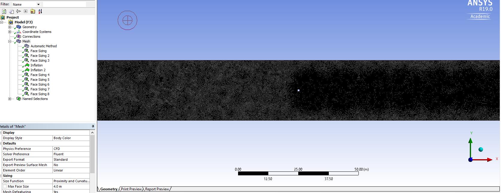
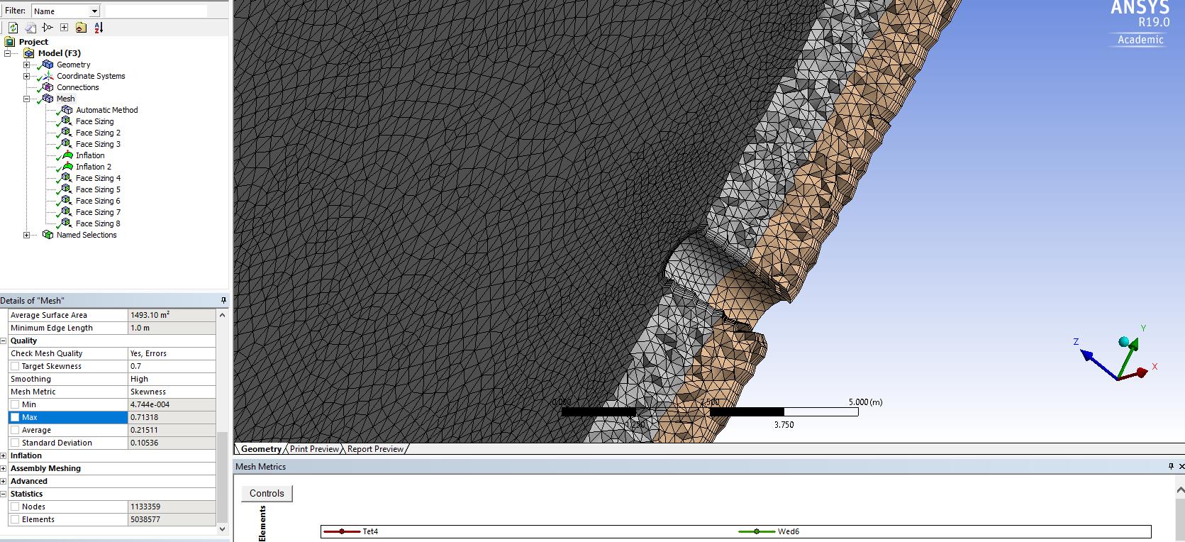
I am not being able to export the mesh to Fluent. It gives me a message in ANSYS Meshing about "Selective Meshing" and then it takes so much time to export and eventually, ANSYS Meshing becomes irresponsive.
MESSAGE: The selective body meshing is not being recorded, so the meshing may not be persistent on an update. If you want to record the order of the body meshing, please use the Mesh Worksheet to track the meshing steps. Please see Selective Meshing documentation for more details.
At first, I click on "Mesh" -> Show body and then Generate mesh. After doing this, when I try to export it, I am not able to do so.
I used "Worksheet" initially. Is it because of that?
Thank you
With regards
Shaheen
-
December 10, 2018 at 4:34 am
peteroznewman
SubscriberDear Shaheen,
In Meshing, click on the Mesh item in the Outline and RMB and Clear Generated Data. Then RMB and Generate Mesh.
That avoids Selective Meshing which occurs when you RMB on a single body and say Generate Mesh on Selected Bodies; don't do that. Don't use the Worksheet.
After the meshing is complete, close Meshing. In Workbench if you have a lightening bolt on Mesh, RMB on Mesh and Update. If you have a Refresh icon, then click on the Refresh button. Only when you have a green check mark on Mesh should you launch Fluent. Not before.
Regards,
Peter -
December 10, 2018 at 4:56 am
Keyur Kanade
Ansys Employeeif you are stuck with only mesh export, please check if there are any overlapping named selection. use right click on named selection and click fix overlapping named selection.
-
December 10, 2018 at 10:02 am
-
December 10, 2018 at 10:05 am
-
December 10, 2018 at 11:31 am
José Mantovani
SubscriberHello Shaheen.
In a domain where the cylinder is the width of the domain, an infinite cylinder analysis is configured. The same idea of an infinite wing in wind tunnel, I suggest that in this case use a 2D domain which will reduce the domain, accelerate the calculations and can achieve a result with greater accuracy. With this approach you can use a circular domain which facilitates a finer mesh in the cylinder region.
If you are interested in analyzing the vortices at the ends of the cylinder, the domain must be wider than the cylinder so a finite cylinder analysis will be configured and the 3D approach is required.
Best Regards,
Mantovani.
-
December 10, 2018 at 4:48 pm
Rob
Forum ModeratorIf you right click on the "Mesh" part of the tree in Meshing you can Show overlapping Named Selections (NS). NS are really useful in Fluent as they define the separate boundary labels so setting up is much easier.
-
December 11, 2018 at 10:16 am
shaheen wahab
SubscriberYes, indeed they are really helpful in Fluent for setting up BCs.Thank you, Rob, I checked for overlapping named selection, but there were none. So, I deleted the previous NS and then re-named them.
With regards
Shaheen
-
December 11, 2018 at 10:20 am
-
- The topic ‘Suggestions to improve mesh quality’ is closed to new replies.
-
5039
-
1749
-
1387
-
1248
-
1021
© 2026 Copyright ANSYS, Inc. All rights reserved.


