-
-
October 28, 2023 at 8:49 am
Aras karimi
SubscriberHi to all,
I want to create a periodic mesh on the domain below, and the front page of the domain (purple color) will be named Periodic 1 and the back page of the domain (blue color) will be named Periodic 2:
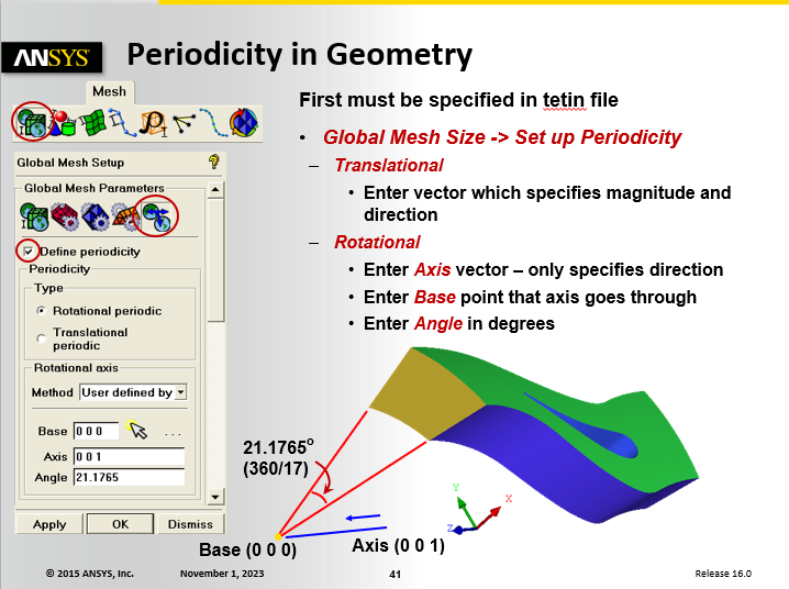
I need to establish a Translational Periodic boundary condition. I created a mesh structure. Now please help how can I apply this boundary condition?
The front surface of the domain is located at the origin of the coordinates, and the back surface of the domain is located in the -Z direction and at a distance of -0.2 meters from the origin of the coordinates. (In other words, the span length of the airfoil is 0.2 meters)
Earlier, I read that I should first come to this section and select the type of boundary condition. There is also a parameter called offset. What number should be written?
And what should I do next?
Thank you for helping me
Regards
-
October 30, 2023 at 6:34 am
Keyur Kanade
Ansys EmployeeOffset in Translation periodic should be distance between two periodic surfaces.
Please go through help manual for more details
Regards,
Keyur
How to access Ansys Online Help Document
Guidelines on the Student Community
Fluids Engineering Courses | Ansys Innovation Courses
-
October 30, 2023 at 7:14 am
Aras karimi
SubscriberThe distance between the two surfaces is 0.2 meters, the front surface is located at the origin of the coordinates and the back surface is located at -0.2 meters from the origin of the coordinates, in other words, the back surface is located in -Z.
Now, there are three zeros in the offset section. Does that mean three values should be written here?
What numbers should I write?
please help me
Thank you
-
-
October 30, 2023 at 11:19 am
Keyur Kanade
Ansys EmployeeThree zeros are for X, Y and Z respectively
Regards,
Keyur
How to access Ansys Online Help Document
Guidelines on the Student Community
Fluids Engineering Courses | Ansys Innovation Courses
-
October 30, 2023 at 12:43 pm
Aras karimi
Subscriberwell i know
What number should I write now?
Should I put 0 0 -0.2 or 0 0 0.2 ?
Don't I need to write values for x and y?
-
November 1, 2023 at 10:24 am
Aras karimi
SubscriberDear Keyur,
The front surface of the domain is located at the origin of the coordinates, and the back surface of the domain is located in the -Z direction and at a distance of -0.2 meters from the origin of the coordinates. (In other words, the span length of the airfoil is 0.2 meters)
I went to ICEM Help and found the following:
I'm still confused and I don't know what number should I put for the offset ?
If you help me, I will thank you a thousand times.
Regards
-
-
November 1, 2023 at 1:07 pm
Keyur Kanade
Ansys EmployeeAs it is parallel to XY plane, you do not need X and Y values.
Regards,
Keyur
How to access Ansys Online Help Document
Guidelines on the Student Community
Fluids Engineering Courses | Ansys Innovation Courses
-
November 1, 2023 at 2:55 pm
Aras karimi
SubscriberShould I put 0 0 -0.2 or 0 0 0.2 for offset?
-
November 2, 2023 at 3:22 am
Aras karimi
SubscriberDear Keyur,
Should I put 0 0 -0.2 or 0 0 0.2 for offset?
-
-
November 2, 2023 at 3:53 am
mjmiddle
Ansys EmployeeThe negative or positive value does not matter. You can use either 0 0 -0.2 or 0 0 0.2.
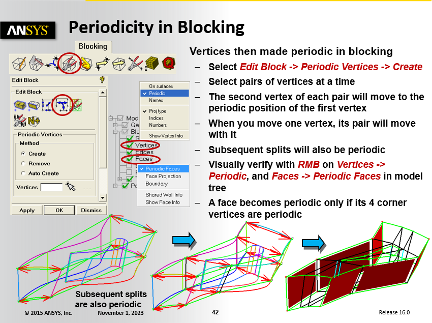
It just defines a distance when node locations will be linked to be the same values in the directions normal to this vector and matching in vector length distance along the vector. After setting up the periodicity direction in the global settings, you must still link the block vertices. This is shown in the ICEM CFD training. Two lectures slides are shown below. The example shows angular periodicity, but the procedure is the same for linear periodicity:
You will need to design your blocking scheme so that the face structure matches at the periodic faces.
-
November 2, 2023 at 4:43 am
Aras karimi
SubscriberThank you
According to the type of blocking I posted earlier, will the following happen?
(You will need to design your blocking scheme so that the face structure matches at the periodic faces.
And is my blocking correct for this?
-
November 2, 2023 at 5:06 am
Aras karimi
SubscriberDear mjmiddle,
For another case, I need to create a symmetry boundary condition between the front and back surfaces of the domain.That is, the front surface of Symmetry1 and the back surface of Domain Symmetry2.
For this situation, do I not need to set the Global Mesh Setup? And only and only in the Part Boundary Conditions section, should I define two surfaces symmetrically?
I mean, in order to create a symmetric boundary condition, there is no need for special work like creating a periodic boundary condition?
Regards
-
-
November 2, 2023 at 5:01 am
mjmiddle
Ansys EmployeeIf you understand the direction you want to make periodic, you should be able to answer this question yourself. So to test you, what do you think? Do you forsee problems with setting up the periodicity? Start linking the vertices as desribed in the two training pages and you'll find out.
-
November 2, 2023 at 5:17 am
Aras karimi
Subscriber -
November 2, 2023 at 5:55 am
Aras karimi
SubscriberDear mjmiddle,
For another case, I need to create a symmetry boundary condition between the front and back surfaces of the domain.That is, the front surface of Symmetry1 and the back surface of Domain Symmetry2.
For this situation, do I not need to set the Global Mesh Setup? And only and only in the Part Boundary Conditions section, should I define two surfaces symmetrically?
I mean, in order to create a symmetric boundary condition, there is no need for special work like creating a periodic boundary condition?
Regards
-
-
November 2, 2023 at 6:58 am
mjmiddle
Ansys EmployeeThe boundary conditions for solver ouptuts are a convenience for setup to the solver. You don't need to set any of those in ICEM CFD. You can set them up entirely in the solver. ICEM CFD only has a very limited selection of BC conditions for output to the solvers anyway. And they are different for each solver and specific to each solver.
A symmetry BC means typically a mirror symmetry, as though you mirrored the model across a plane into empty space. There is no linking to set up. There is no symmetry1 and symmetry2 that are linked in this case. You are getting the solver term "symmetry" mixed up with the "periodicity" term in ICEM CFD.
As far as specifying 0 0 -0.2 or 0 0 0.2 for the linear periodicity, they are both vectors along the same line in space. Only the direction is flipped. But direction is not important. The mesh is equal on both periodic sides when you link the vertices of the blocking. They are coupled. It chooses one side as the master, which you don't always know ahead of time until you try to change edge params on one side and you find out which side has the effect.
-
November 2, 2023 at 7:17 am
Aras karimi
SubscriberThank you very much, Dear mjmiddle, for your reply and your time.
I only have two other small problems with the meshing. Should I ask in the same topic ([ICEM] Airfoil Meshing in icem-cfd) ?
-
November 2, 2023 at 8:07 am
Aras karimi
SubscriberDear mjmiddle ,
In the new thread below I have raised a problem when studying the independence of the solution from the mesh:
(/forum/forums/topic/mesh-independence-study-4/#post-314495)
I will be grateful if you help me
Thank you a thousand times
-
November 18, 2023 at 3:42 pm
Aras karimi
SubscriberHi Dear mjmiddle,
I want to create mesh and periodic boundary condition for another mode.
This time, the front page of the flow is at Z= -0.7mm and the back page of the flow is at Z= -40.7mm. That is, the length of the airfoil span is 40mm.
What number should I put for the offset?
-
November 20, 2023 at 5:42 pm
Aras karimi
SubscriberHi Dear mjmiddle,
I want to create mesh and periodic boundary condition for another mode.
This time, the front page of the flow is at Z= -0.7mm and the back page of the flow is at Z= -40.7mm. That is, the length of the airfoil span is 40mm.
What number should I put for the offset?
-
-
November 21, 2023 at 6:53 pm
Govindan Nagappan
Ansys EmployeeAras, You can use the same logic that you used for the first model. If the periodic faces are offset by a distance of 40mm in Z direction, you can enter offset of 0 0 40
-
- The topic ‘Creation of Periodic B.C in ICEM’ is closed to new replies.


-
5179
-
1838
-
1387
-
1249
-
1021

© 2026 Copyright ANSYS, Inc. All rights reserved.


