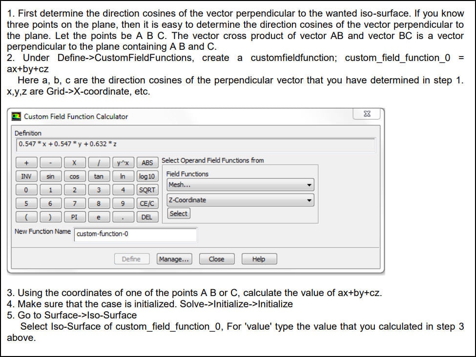
-
-
September 28, 2018 at 3:44 pm
vguda
SubscriberI have a cylinder with the inlet face oriented in YZ direction. The length is along X direction. Say this cylinder is now rotated about Y direction 50 deg. I want to create an iso surface in the center plane along the length in the new axes. How to do it.
If the cylinder is in regular orientation, i can say create iso surface in constant z . Now since it is rotated how to do it?
If the geometry has parts oriented in different directions, is there a way to create one iso-surface or plane to represent the entire geom to view the flow
-
September 28, 2018 at 4:33 pm
raul.raghav
SubscriberMoving this to the “Result Visualisation” thread.
You can create a plane by prescribing 3 points. So a cross-section normal to the Z-axis of your original cylinder can be created by prescribing 3 points:
(i) 0, 0, 0
(ii) 0, y, 0
(iii) x, 0, 0
Now if you rotate the cylinder along the Y-axis by 50deg, the 3 points required to create the mid-plane normal to the Z-axis would become:
(i) 0, 0, 0
(ii) 0, y*cos(50), 0
(iii) x, 0, 0
Is this what you’re looking for? -
October 1, 2018 at 4:51 am
-
Viewing 2 reply threads
- The topic ‘Defining iso-surface in a different orientation other than x, y and z’ is closed to new replies.

Innovation Space
Trending discussions
Top Contributors
-
6510
-
1906
-
1458
-
1308
-
1022
Top Rated Tags
© 2026 Copyright ANSYS, Inc. All rights reserved.
Ansys does not support the usage of unauthorized Ansys software. Please visit www.ansys.com to obtain an official distribution.