-
-
September 9, 2023 at 8:33 pm
javat33489
SubscriberHi all.
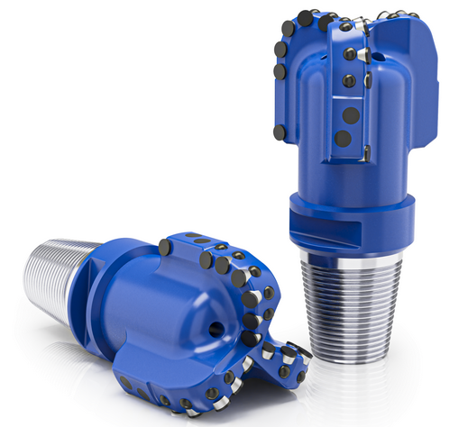
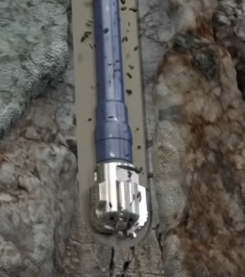
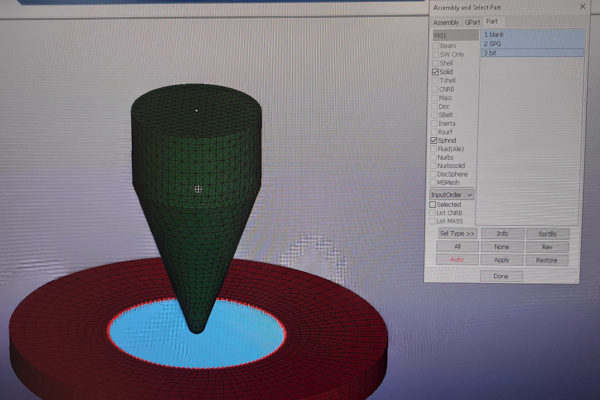
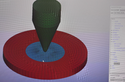
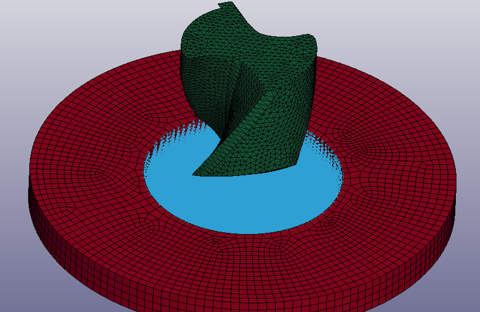
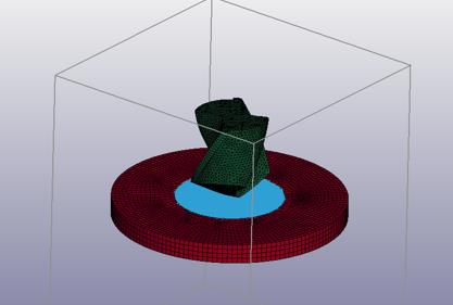
I began to solve the problem of drilling rock with a chisel. The bit has attachments. The goal is to study the nozzles, how they heat up and deform.
The entire body of the bit is a rigid body. Nozzles are unformable bodies. The rock is SPH particles. It is necessary to evaluate the condition of the nozzles, for example, after 500 meters of drilling. It is impossible to carry out the calculation, because it needs to be carried out not in milliseconds, but in seconds, so that the nozzles experience real stress during rotation. If you carry out the calculation in milliseconds and set the real rotation speed, the nozzles are greatly distorted because the speed increases by 1000.
The time required to solve the problem with 1 second of calculation is 20k hours. To reduce the solution time, you need to reduce the calculation time or increase the density. A strong increase in density (for example, by 1000 or 10,000) leads to inadequate results, while a decrease sometimes leads to distortion of deformable bodies.
It turns out a vicious circle:
You can't increase the density (too much), but the calculation time is unrealistic.
Use a powerful cluster, but it will not increase the speed by millions of times.
Apply the usual method, but there is a big loss of energy.
Use SPG, but the method is much more complicated.
Increase the size of the elements, but there will be no accuracy.
Use a small sector, but it is difficult to transfer to the entire model.
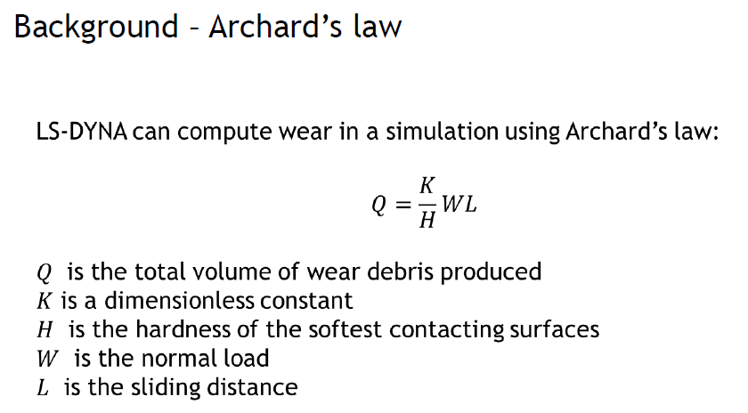
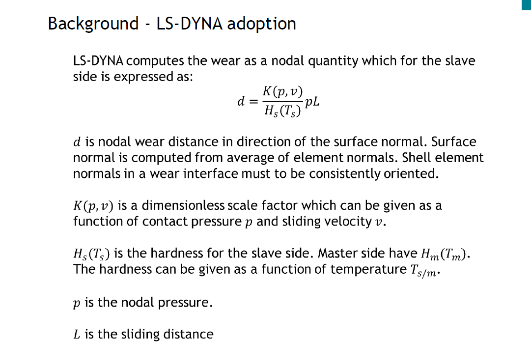
My question is this. There is a method for determining the voltage and temperature on the surface of a rigid body. I want to make both the chisel and attachments rigid bodies and use the ADD_WEAR card. Tell me how to determine stress and temperature on the surface of a rigid body?
If there is another way to solve this problem, tell me? Thank you.
-
September 12, 2023 at 4:06 pm
Reno Genest
Ansys EmployeeHello,
I would investigate the SPG method for this application. We have successfully modeled a screw in concrete with SPG and increasing the density of the concrete to speed up the calculation was not an issue. You will find a training course on failure and SPG on the Ansys Learning Hub (ALH):
https://jam8.sapjam.com/groups/Pw2mREtAJtrrAUXfMhYrQg/overview_page/LbYuRERahsNwxBSCNtflN8
Also, you will find information on wear here:
http://ftp.lstc.com/anonymous/outgoing/support/EXAMPLES/wear_for_distribution_with_pdf.tar.gz

And here:

https://www.dynalook.com/conferences/14th-international-ls-dyna-conference/simulation/simulation-of-wear-processes-in-ls-dyna-r/view


Reno. -
September 12, 2023 at 7:52 pm
javat33489
Subscriber>> We have successfully modeled a screw in concrete with SPG and increasing the density of the concrete to speed up the calculation was not an issue.
Please send me the project file?
___
Is it possible to greatly increase the density in the SPG method, unlike SPН? -
September 12, 2023 at 8:42 pm
Reno Genest
Ansys EmployeeHello,
Ansys employees are not allowed to upload models on the Ansys Forum.
You will find similar examples with SPG here:
https://www.lstc-cmmg.org/spg
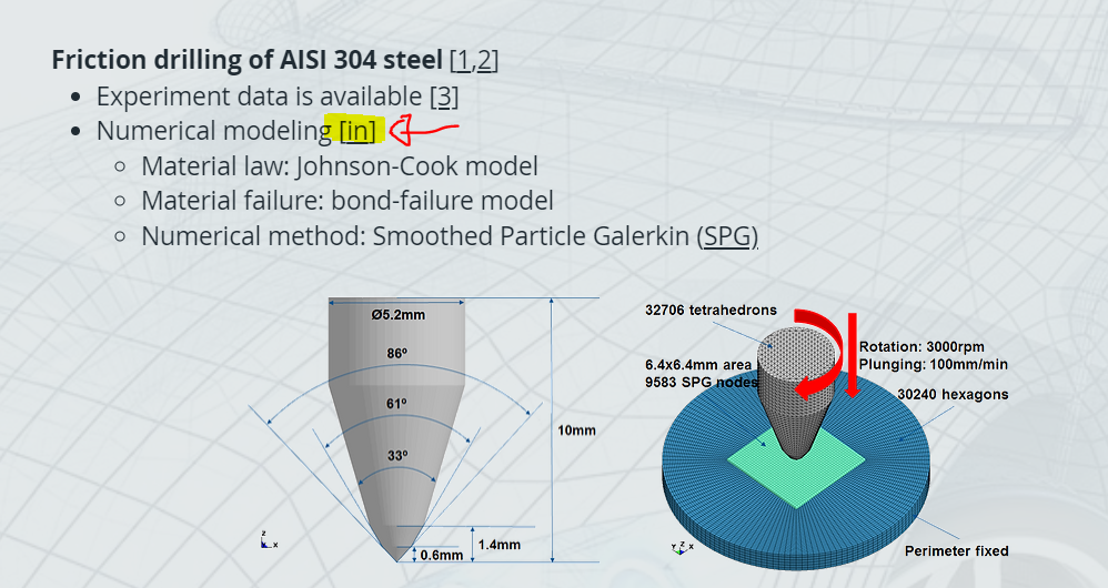
https://www.lstc-cmmg.org/drilling
You can download the model by clicking on the [in]:
When you increase the mass of your model, it is your responsibility to verify that the results are valid with the increased mass (higher density). One way to do it is by running the same model with no mass increase.
Reno.
-
September 13, 2023 at 6:55 pm
-
-
September 13, 2023 at 7:06 pm
Reno Genest
Ansys EmployeeHello,
I don't know what you mean by "map" or "maps" and "setting values in maps based on the material used?"?
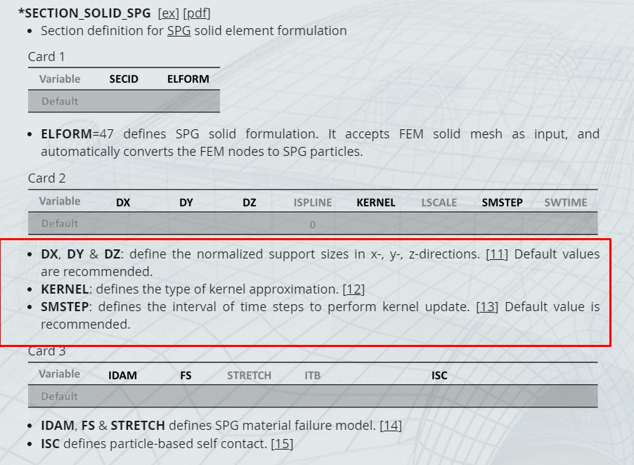
If you leave the parameters (DX, DY, DZ, KERNEL, SMSTEP, etc.) blank on the *SECTION_SOLID_SPG keyword, the LS-DYNA solver will use the default values. You can start with the default values and see what you get.
Do you have access to the SPG training on the Ansys Learning Hub? In the training, you will find SPG setting recommendations based on certain applications.
The material model is independent of the *SECTION_SOLID_SPG. The only material information you need to specify in the *SECTION_SOLID_SPG is the material failure (IDAM, FS, and STRETCH). Please refer to the training material and the LS-DYNA user manual for more information.
Reno.
-
September 14, 2023 at 7:55 pm
-
September 15, 2023 at 4:50 pm
javat33489
SubscriberIt turns out that Ansis cannot yet perform drilling calculations with an analysis of the durability of drill bits at the present time. This could be SPH or SPG;
calculations in the C system in seconds are not realistic even on a powerful PC.
-
-
September 15, 2023 at 8:51 pm
Reno Genest
Ansys EmployeeHello,
I think it is possible in LS-DYNA as we successfully simulated drilling in concrete using SPG; this is a similar process. You need to increase the density of the rock material to speed up the calculation.
Give it a try and let me know how it goes.
Reno.
-
September 15, 2023 at 8:54 pm
Reno Genest
Ansys EmployeeHello,
If you have a commercial license of Ansys LS-DYNA, please create a support case on the Ansys Customer Support Space (ACSS) and we will send you an example model:
https://customer.ansys.comYou will find a short course on how to register to the new ACSS here:/courses/index.php/courses/ansys-customer-support-space/lessons/registering-for-the-ansys-customer-support-space/If you don't have a commercial license, then maybe another user will be able to share an example model with you.Reno. -
September 15, 2023 at 9:04 pm
Reno Genest
Ansys EmployeeHello,
You can search the litterature to see how others have done rock cutting or drilling before. There are some papers on dynalook.com:
https://www.dynalook.com/conferences/13th-european-ls-dyna-conference-2021/geomechanics/nasouri_university_of_texas-2.pdf/view
https://www.dynalook.com/conferences/15th-international-ls-dyna-conference/spg/smoothed-particle-galerkin-method-with-a-momentum-consistent-smoothing-algorithm-for-coupled-thermal-structural-analysis/view
https://www.dynalook.com/conferences/15th-international-ls-dyna-conference/spg/parametric-and-convergence-studies-of-the-smoothed-particle-galerkin-spg-method-in-semi-brittle-and-ductile-material-failure-analyses/view
Reno.
-
September 15, 2023 at 9:14 pm
Reno Genest
Ansys EmployeeHello,
How long is the duration of the drilling? How many seconds? We simulated a screw in wood that lasted 2.4 seconds. You can use the following strategies to speed up the calculation:
- Increase the density of the rock.
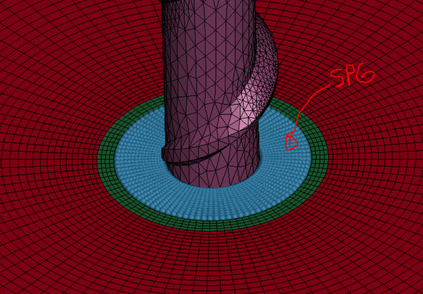
- Limit the SPG domain to only where you need it (see image below).
- Use *CONTROL_MPP_DECOMPOSITION_ARRANGE_PARTS so distribute the SPG part to all processors.
- Run the calculation on a cluster using MPP LS-DYNA with 32, 64, or more processors.
Let me know how it goes.
Reno.
-
September 16, 2023 at 9:29 pm
javat33489
SubscriberThank you very much for the links and advice. I'll try again.
>> Increase the density of the rock.
Can I change the density for just the stone? Should the density for the deformable body of the drill be left the same?
>>How long is the duration of the drilling? How many seconds? We simulated a screw in wood that lasted 2.4 seconds.
2.4 seconds is enough for me too
-
September 18, 2023 at 8:38 pm
Reno Genest
Ansys EmployeeWhat is controlling the timestep? I assume the SPG particles were, but maybe it is the deformable body of the drill? The first step would be to make sure you have a uniform size mesh and you don't have small elements here and there. If you have small elements, try to remesh to get a more uniform mesh. The small elements will control the timestep.
What are you interested in the drill? Could you model the drill as fully rigid and calculate the wear using the contact?
We usually increase the density of the SPG material only, which is initially at rest. We have to be careful when increasing the density of the deformable components of the drill. This will increase the kinetic energy of the system and may affect the results. You can do some tests and change the density and see if it affects the results you are interested in.
Reno.
-
-
September 18, 2023 at 1:04 pm
javat33489
Subscriber-
September 18, 2023 at 8:42 pm
Reno Genest
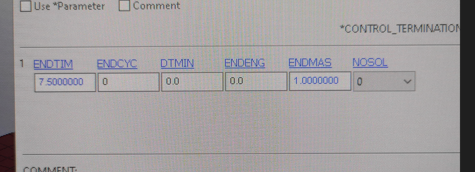
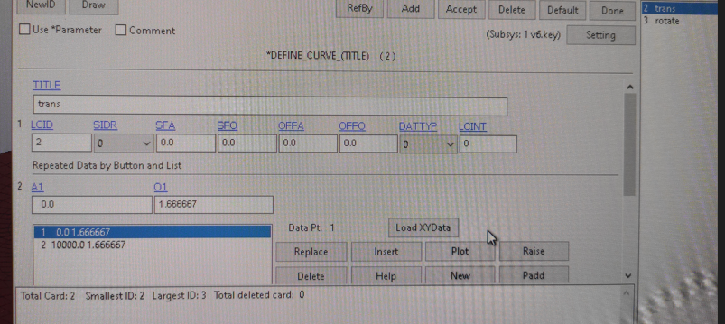
Ansys EmployeeIt is a best practice to extend the *DEFINE_CURVE beyond the termination time. Here, the value is constant and it does not make any difference if the last point on the curve is 10 000, 1000, or 100, or even 10 ms. As long as the last point on the curve is beyond the termination time of 7.5ms.
If you don't extend the curve beyond 7.5ms, you might run into issues. You can try it. Because, the LS-DYNA calculation will almost always go beyond the termination time. How far beyond the termination time depends on the timestep. And, for the calculation happening beyond the termination time, the LS-DYNA solver will not know what value to use and it will be reset to zero.
Reno.
-
-
September 18, 2023 at 7:05 pm
javat33489
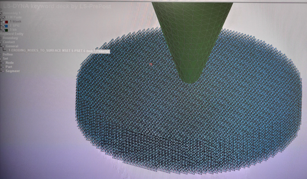
SubscriberIn addition, in the LSTK project, I noticed that they use contact between the drill and LNG AUTOMATIC_NODES_TO_SURFACE, and I use ERODING, which increases the time for solving the problem by 10 times. But the AUTOMATIC_NODES_TO_SURFACE contact does not determine the cutting of particle cells after the first layer; the remaining layers penetrate into the drill. Why do they use it? -
September 18, 2023 at 8:44 pm
Reno Genest
Ansys EmployeeBecause NODES_TO_SURFACE contacts are recommended with SPG particles. You could use a NODES_TO_SURFACE contact and put all the SPG particles in the node set for the contact. This way, all particles will be in contact with the surfaces (segments) of the drill.
Let me know how it goes.
Reno.
-
September 19, 2023 at 7:01 pm
javat33489
SubscriberThank you very much for your answers. They are very helpful!
>>What is controlling the timestep? I assume the SPG particles were, but maybe it is the deformable body of the drill? The first step would be to make sure you have a uniform size mesh and you don't have small elements here and there. If you have small elements, try to remesh to get a more uniform mesh. The small elements will control the timestep.
all is clear, thank you
>>What are you interested in the drill? Could you model the drill as fully rigid and calculate the wear using the contact?
This is one of the best pieces of advice right now. I'd like to do that too. Using CONTACT_ADD_WEAR contact and calculating wear. But will it be enough? This will be wear in the contact and not on the drill.
My task is this: there are attachments on the drill, my goal is to examine these attachments for wear and temperature after drilling a certain interval. When we model drills, we distribute the nozzles on its surface and do not immediately understand which of the nozzles will be loaded more heavily and which less, our goal is for all the nozzles to be loaded with sharp rock.
Using the calculation, I want to find out which nozzles have worn out and heated up faster, after which I will change their location and size and run the calculation, etc.
Tell me, will it be enough to examine the contact for wear using attachments in the form of a rigid body? That would be great! Will I be able to track the temperature on the surface of the nozzles?
>> We usually increase the density of the SPG material only, which is initially at rest. We have to be careful when increasing the density of the deformable components of the drill. This will increase the kinetic energy of the system and may affect the results. You can do some tests and change the density and see if it affects the results you are interested in.
all is clear, thank you
>> It is a best practice to extend the *DEFINE_CURVE beyond the termination time. Here, the value is constant and it does not make any difference if the last point on the curve is 10 000, 1000, or 100, or even 10 ms. As long as the last point on the curve is beyond the termination time of 7.5ms.
If you don't extend the curve beyond 7.5ms, you might run into issues. You can try it. Because, the LS-DYNA calculation will almost always go beyond the termination time. How far beyond the termination time depends on the timestep. And, for the calculation happening beyond the termination time, the LS-DYNA solver will not know what value to use and it will be reset to zero.
Now everything is clear to me.
Thank you. My tool rotates at 26 rad/s and the feed speed is 40 mm/s. I want to test my speeds on this task from LSTK. Can I leave the solution time at 7.5, set the rotation speed to 26 (at a time of 10,000), and set the feed to 40 (at a time of 10,000). Will this be logical for the program?
-
September 19, 2023 at 7:13 pm
javat33489
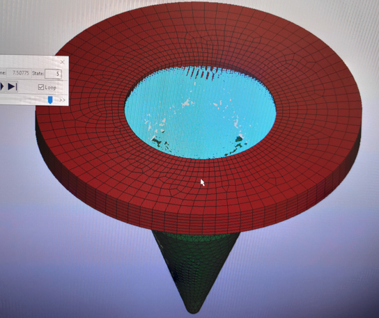
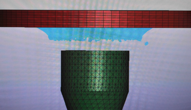
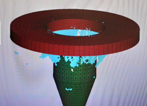
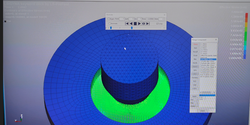
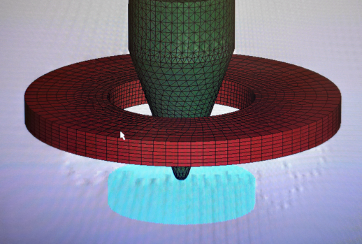
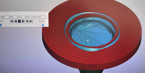
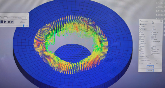
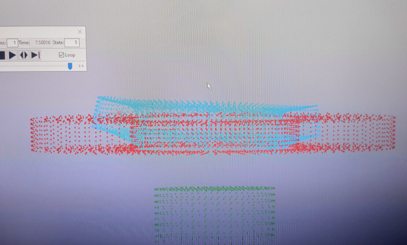
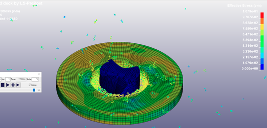
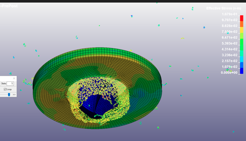
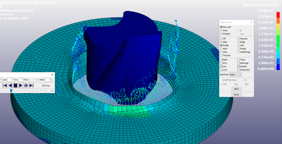
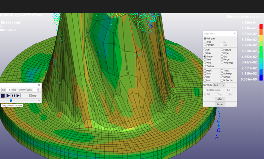
SubscriberI thought so too. And I did some tests. Despite the fact that I selected all the particles for drilling, the AUTOMATIC contact worked with penetration into the rigid body, and the ERODED contact worked without penetration, but the solution time was 12 times longer. I use 48 cores to solve a problem. I'll show you the screenshots.
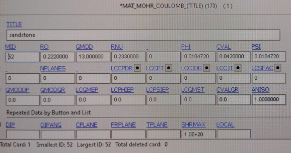
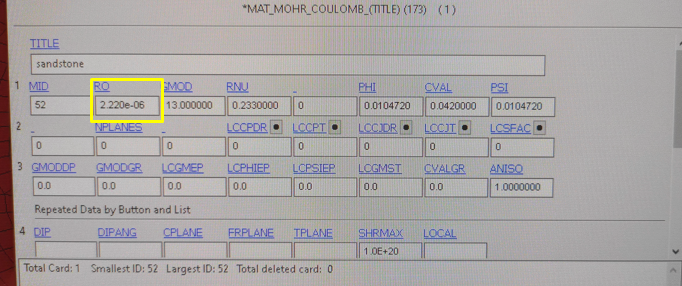
I used the material Mor-Columb sandstone, I increased the density like that of LSTC:
Calculation using AUTOMATIC contact:
Calculation using ERODED contact:
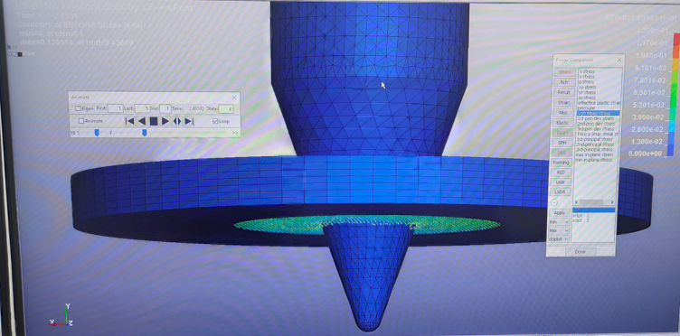
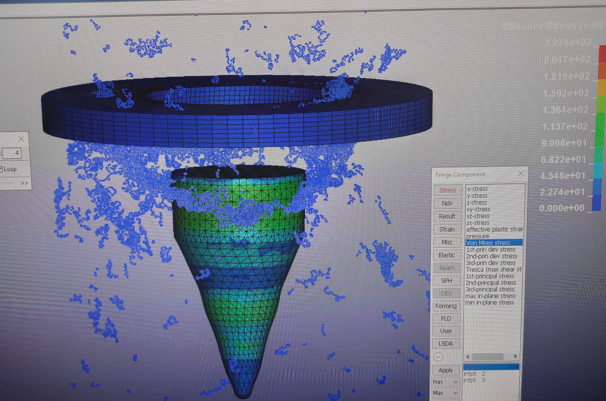
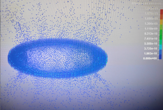
By the way, the voltages are very small. This is fine?
Then I reduced the density to the one required for the selected system of units, the calculation time increased many times, but for me it is doable. A rigid drill squeezes particles out of the ring, drilling does not occur:
-
September 19, 2023 at 7:38 pm
javat33489
SubscriberWhat do you say sir?
-
-
-
September 19, 2023 at 7:13 pm
Reno Genest
Ansys EmployeeHello,
You will have to do some tests to see if the wear approach is good enough. I would start with a rigid drill to simplify the model and run faster and see what you get. Then, you can have flexible parts on the drill and compare.
The hardness can be a function of temperature. Will this be enough? I don't know. It is for you to find out.
Reno.
-
September 20, 2023 at 2:05 am
javat33489
SubscriberOk sir I will try. Thank you.
Can you give me recommendations for my speeds? I wrote:
>>Thank you. My tool rotates at 26 rad/s and the feed speed is 40 mm/s. I want to test my speeds on this task from LSTK. Can I leave the solution time at 7.5, set the rotation speed to 26 (at a time of 10,000), and set the feed to 40 (at a time of 10,000). Will this be logical for the program?
I also posted screenshots in the second message. What can you say about them (see message above)? Thank you!
-
September 20, 2023 at 7:42 pm
javat33489
SubscriberI have a few more questions. But soon I'll figure it all out. We still need your help.
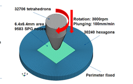
In the LSTC project, the rotation speed is 3000 rpm and the feed speed is 100 mm/min.
But in the program they specified a feed speed of 1.6 mm at a time of 10 seconds, and a rotation speed of 3.14 rad/s at a time of 10 seconds.
Why? 3000 rpm = 314 rad/sec, why did they divide by 100? .
How can I use my data? I have a rotation speed of 27 rad/s and a feed speed of 40 mm/s (rock drilling). 40 mm/s is so fast that the drill does not see the particles and flies right through.
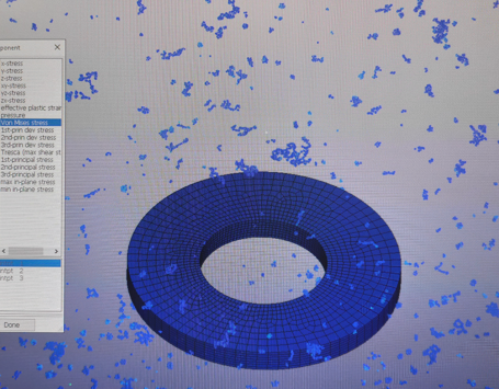
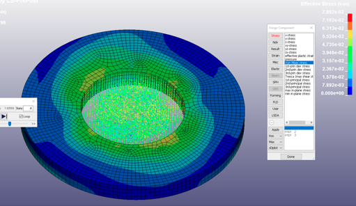
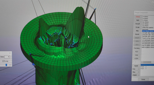
I also tried using a deformable body instead of a rigid one. The calculation passed, but the stresses are very small, as I understand it they are in Pa? If it were MPa it would be logical. Why are they so small? I also used increased density as in LSTC
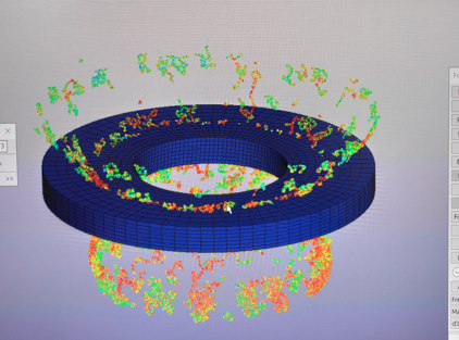
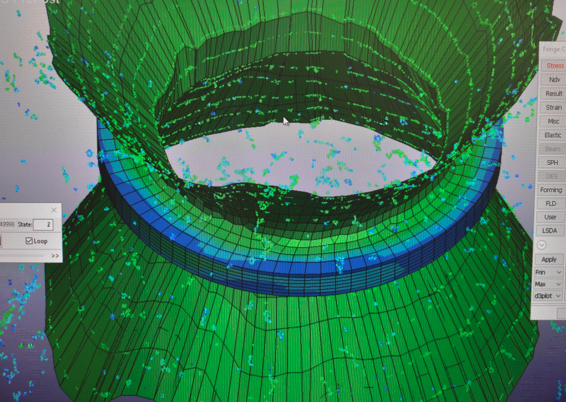
Why does the ring not deform or experience stress? It is connected by TIED by contact with particles:
-
-
September 20, 2023 at 8:01 pm
Reno Genest
Ansys EmployeeHello,
In your model, you have to make sure you use consistent units. If you don't, your results won't be valid. LS-DYNA expects consistent units. Here is more information:
https://lsdyna.ansys.com/consistent-units/
If your unit system is in Pa, then the results will be in Pa. If your unit system is in MPa, then the results will be in MPa.
Reno.
-
September 20, 2023 at 8:08 pm
Reno Genest
Ansys EmployeeI don't know why the model has a rotation speed of 3.14 rad/s. Maybe it is a typo?
I would use your own rotation and feed speed for your model. If the drill does not "see" the particles, then you have a contact problem and you need to troubleshoot it. Look at the SPG training on ALH to see which contacts are recommended with SPG particles. Are you using the right contact type? Is the contact defined properly? Have you tried increasing the contact stiffness? What about bucket sort frequency? Have you tried reducing TSSFAC? You will find more information about contacts here:
https://www.oasys-software.com/dyna/wp-content/uploads/sites/2/2020/01/Intro-to-Contacts.pdf
https://ftp.lstc.com/anonymous/outgoing/support/FAQ_docs/contact.pdf
Reno.
-
September 20, 2023 at 8:11 pm
Reno Genest
Ansys Employee-
September 21, 2023 at 7:28 pm
javat33489
Subscriber>> In your model, you have to make sure you use consistent units. If you don't, your results won't be valid. LS-DYNA expects consistent units. Here is more information:If your unit system is in Pa, then the results will be in Pa. If your unit system is in MPa, then the results will be in MPa.
Oh sir! You're right. I made a childish mistake and forgot about units. I checked the dimensions of the geometry and they match, everything is ok. I also checked by units and my pressure is in GPa.
Thus, 2 GPa is a lot for a drill. But if it is a Rigid body, then I see only 150 MPa on the concrete. This is good. I think I need to think about how to use a rigid drill bit and remove stress and heat from the contact.
>>Look at the SPG training on ALH to see which contacts are recommended with SPG particles. Are you using the right contact type? Is the contact defined properly? Have you tried increasing the contact stiffness? What about bucket sort frequency? Have you tried reducing TSSFAC? You will find more information about contacts
here:https://www.oasys-software.com/dyna/wp-content/uploads/sites/2/2020/01/Intro-to-Contacts.pdf
https://ftp.lstc.com/anonymous/outgoing/support/FAQ_docs/contact.pdf
Thank you sir. Yes, I saw it and tried it. But I will try again.
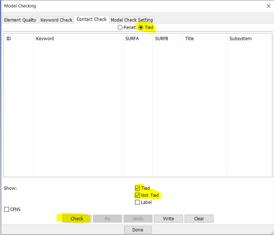
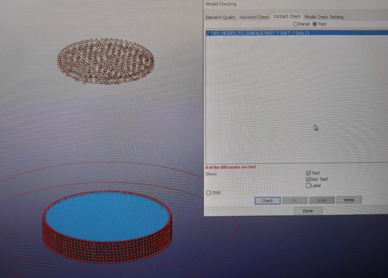
>>Is the tied contact between the SPG particles and the FEM ring working? Are the SPG particles (nodes) tied? You can use the Model Checking application in LSPP to check the contacts:
Also, post-process the results only on the ring (show only the ring part in LSPP). Do you see results?
Yes sir I checked the contact, it is connected
I also left only the ring, there is 0 stress on it
-
September 21, 2023 at 7:37 pm
javat33489
SubscriberI have one more question sir.
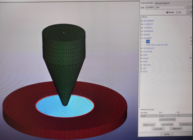
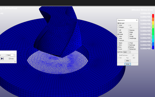
Previously, I created geometry in WB and exported it to LS-Dayna pre. When I prepared geomtrey in WB, I immediately indicated the core with particles. And when I opened it in LS-Dayna pret, I got SPH particles:
Despite the fact that I indicate solid_spg in PART, I think that the calculation is still based on SPH particles. Right?
________________________
The second time I did not indicate the core as particles in WB, and left the SOLID element, but in LS-Daina pre I assigned this solid solid_spg and the result turned out to be different. Now the calculation was based on SPG particles. Right?
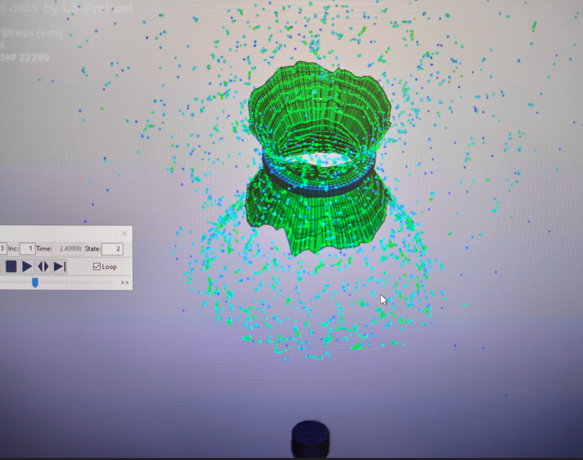
But particles penetrate through the ring:
I look forward to your comments SIR. I think I will be able to solve this problem soon. And your answers will help someone else on the forum.
-
-
September 21, 2023 at 8:28 pm
Reno Genest
Ansys EmployeeHello,
When you mesh your model in WB, mesh the SPG part with regular solid elements. Do not use particle method for meshing as you would do with SPH.
Then, apply the section in Mechanical to have SPG particles on the SPG body. This way, you will have SPG particles.
Note that when using SPG particles, the mesh is still a solid mesh with *ELEMENT_SOLID (there is no *ELEMENT_SPG keyword). The only thing that will decide wheather the mesh is regular FEM or SPG particles is the *SECTION_SOLID_SPG.
Let me know if this helps or not.
Reno.
-
September 21, 2023 at 8:30 pm
Reno Genest
Ansys EmployeeAlso, what is this rock drilling project you are doing? Are you affiliated with a company or a university? If so, which one? Maybe we can help you better outside the Ansys Forum via a regular support case. This way, we will be able to exchange files.
Reno.
-
September 22, 2023 at 7:00 pm
javat33489
Subscriber>> When you mesh your model in WB, mesh the SPG part with regular solid elements. Do not use particle method for meshing as you would do with SPH.
Then, apply the section in Mechanical to have SPG particles on the SPG body. This way, you will have SPG particles.
Note that when using SPG particles, the mesh is still a solid mesh with *ELEMENT_SOLID (there is no *ELEMENT_SPG keyword). The only thing that will decide wheather the mesh is regular FEM or SPG particles is the *SECTION_SOLID_SPG.
Let me know if this helps or not.
Yes sir, that's what I thought. I decided to clarify.
>>Also, what is this rock drilling project you are doing? Are you affiliated with a company or a university? If so, which one? Maybe we can help you better outside the Ansys Forum via a regular support case. This way, we will be able to exchange files.
Sir, I can't do this now. Maybe I'll do it later.
___
I think that soon everything will be clear how to do my task. Thanks to your answers to the questions.
I made contact with the SPH mesh through which my drill flew and did not notice the particles.. The speed is very high (40 mm/s) and concrete particles scatter in all directions. I'll try installing a BOX card and extending the size of the workpiece for drilling. To study more closely how the drill will pass through the thickness of the particles.
The speed is very high (40 mm/s) and concrete particles scatter in all directions.
I'll try installing a BOX card and extending the size of the workpiece for drilling. To study more closely how the drill will pass through the thickness of the particles.
I will do the same test with SPG particles. But I don’t understand why they penetrate the outer ring? Maybe you need to add another contact? To prevent drilled particles from penetrating the outer ring?
I also don’t understand why there is no stress on the outer ring?
-
September 26, 2023 at 8:06 pm
javat33489
SubscriberHello.
I did some more tests.
I also redesigned the LSTC setup, I added a drill instead of a bullet.
I did tests on two particles: SPH and SPG.
1.SPH. First I did a test with a low speed of 0.6 m/s
SPH particles scatter greatly, even the BOX card does not help, because of this the calculation is very slow.
But the calculation is successful, the particles are drilled, the particles pull the ring along with them.
Next, I tried to set the maximum speed for the rock drill, it is 40 m/s and the drill does not see the particles and flies right through. I reduced TSSF to 0.6, I added VDS = 20 in contact, I tried increasing the contact hardness, but it only got worse.
2.SPG. I also performed the calculation at low speed first.
But the calculation is accompanied by NEGATIVE VOLUME warnings. And it ends in failure.
So I have several problems:
1.When calculating at high speed, the drill does not see the contact.
2.When calculating on SPG particles, the errors are NEGATIVE VOLUME and inadequate reaction of particles.
3.The BOX map does not work and the calculation freezes until it calculates particles that fly far away.
4.SPG particles penetrate into the ring, is another contact necessary?
Dear ANSIS experts. If you can help me answer these questions.
I will be able to simulate the drilling process. I can also attach mine to a file hosting service for you to view, please let me know.
After you help me, I can start wearing.
Help me answer the questions, please.
-
-
September 27, 2023 at 12:43 am
Reno Genest
Ansys EmployeeHello,
You need to tackle these problems one by one and troubleshoot. Ideally, you can reproduce the problem on a small and efficient model to run quickly and troubleshoot faster. You could try to use a coarser mesh and/or scale the size of the model to increase the timestep and run faster.
- Try to fix the contact problem.
- Try different contact types (*CONTACT_NODES_TO_SURFACE; *CONTACT_AUTOMATIC_NODES_TO_SURFACE, etc.). Use the node set of the SPG particles as the SURFA and the segment set of the drill surfaces as SURFB.
- Change the SOFT option. Try SOFT=1 (best for SPG).
- Increase the contact stiffness. Set SOFSCL=0.9
- Decrease the bucket sort frequency to 1. Set BSORT=1
- Refer to the presentation on contacts I sent you earlier.
- This may require many trials and errors.
- SPG is a particle method; there is no negative volume. Set ERODE=0 on *CONTROL_TIMESTEP to get rid of those messages.
- I don't know. Try to create a new post for this question.
- You need a TIED contact between the SPG particles and the ring.
Reno.
-
September 27, 2023 at 7:29 pm
javat33489
SubscriberThank you for your responses. They were very helpful.
>>and the segment set of the drill surfaces as SURFB.
Decrease the bucket sort frequency to 1. Set BSORT=1
This helped me when solving with SPH particles
>> Change the SOFT option. Try SOFT=1 (best for SPG).
Yes, for SPG and SPH I use SOFT=1.
>> SPG is a particle method; there is no negative volume. Set ERODE=0 on *CONTROL_TIMESTEP to get rid of those messages.
Yes, of course I use it this way, but negative volume warnings still appear.
>> You need a TIED contact between the SPG particles and the ring.
Yes, of course I do that. I redefined the contact again and everything worked.
___
What I got:
SPG. At low feed speeds, the SPG drill works fine
If I increase the feed speed to 40 m/s, the SPG particles scatter and pull the seal ring with them, which is greatly distorted
SPH.
At low speeds, SPH particles also work normally, but fly away a lot.
When the feed speed increases to 40 m/s, the particles fly away and pull the solid ring behind them and greatly distort it
___
Then I decided to remove the ring and increase the radius of the particle (SPH) circle
The particles fly away monstrously. It happens like this. The drill pierces the particles and goes far down, and the particles begin to fly for the rest of the time until almost all of them fly away. In addition, the stress are very low.
I have not yet conducted such an experiment for the SPG.
___
So, I have a new problem, I hope this is the last. Particles fly away a lot. I will be waiting for your help, thank you.
- Try to fix the contact problem.
-
September 27, 2023 at 10:23 pm
Reno Genest
Ansys EmployeeHello,
Do you have element numbers where the negative error happens? You need to troubleshoot it:
https://ftp.lstc.com/anonymous/outgoing/support/FAQ/negative_volume_in_brick_element.tips
Also, you may have a problem with your material model. I am not a specialist of rock or soil materials. Please create a new post and one of my colleague will be able to help.
Reno.
-
September 28, 2023 at 3:41 pm
Reno Genest
Ansys EmployeeAlso, which LS-DYNA solver are you using? With SPG, it is recommended to use the latest solver MPP double precision.
Reno.
-
September 28, 2023 at 7:03 pm
javat33489
Subscriber>>Also, you may have a problem with your material model. I am not a specialist of rock or soil materials. Please create a new post and one of my colleague will be able to help.
Fine. I did some more tests and will open a new question.
>>Also, which LS-DYNA solver are you using? With SPG, it is recommended to use the latest solver MPP double precision
Yes, that's what I do sir.
Thank you!
-
-
- The topic ‘Rock drilling’ is closed to new replies.


-
4597
-
1495
-
1386
-
1209
-
1021

© 2025 Copyright ANSYS, Inc. All rights reserved.

