TAGGED: structural-analysis
-
-
August 28, 2023 at 5:08 am
M Usman
SubscriberHi everyone, hope you are going well. I have done structural analysis on the circular shape body using two different approaches that are listed as below;
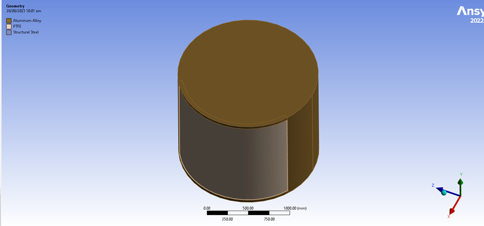
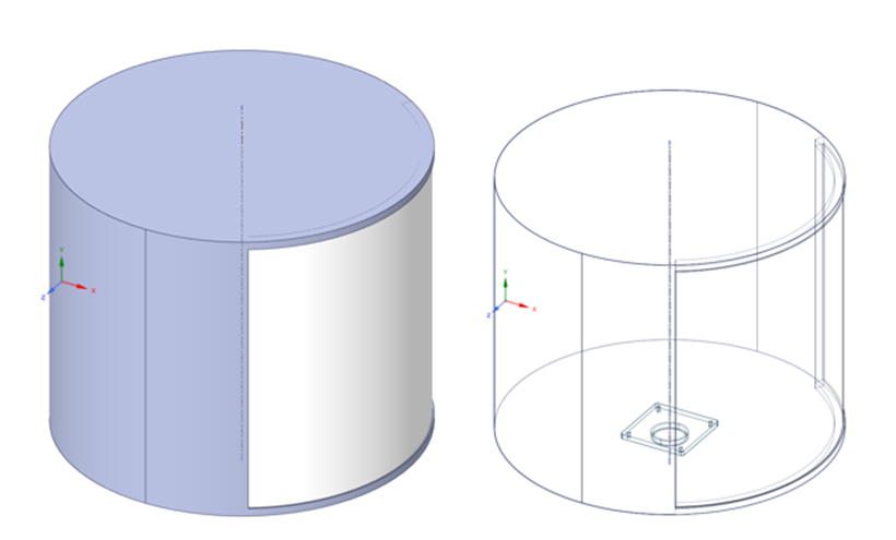
Cad Model Including Simplified Conceptual Cad Model of Aluminum Frame with PTFE Plate at Front
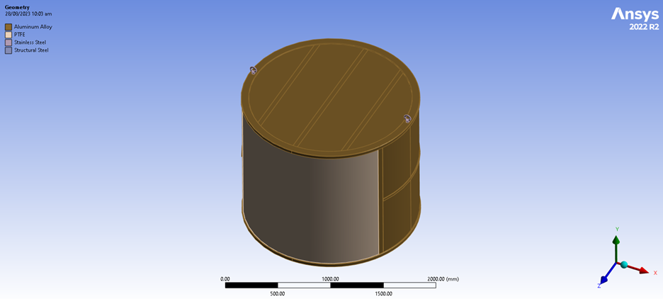
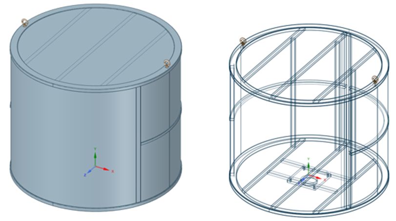
Cad Model Including Actual Manufactured Cad Model of Aluminum Frame with PTFE Plate at Front
Note:
Meshing is same in both cases
Boundary Conditions- Body Weight, Fixed Support & Drag Force due to wind at Front Plate
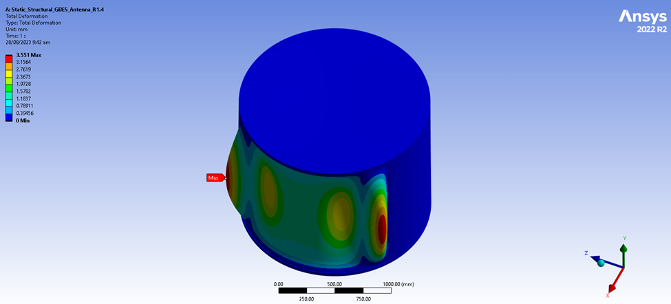
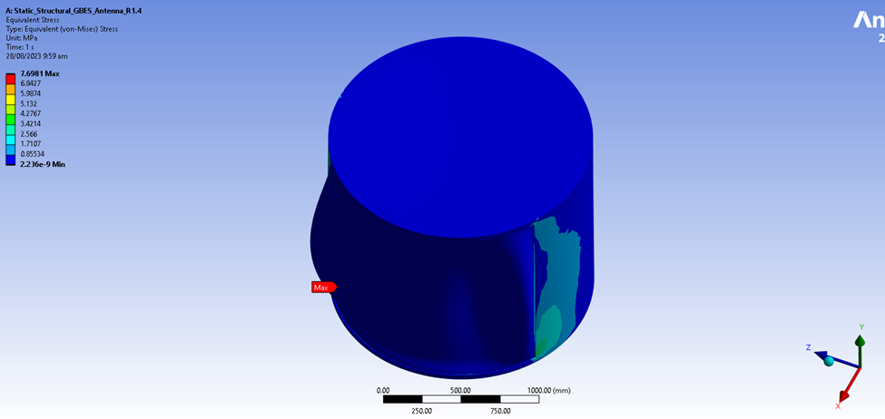
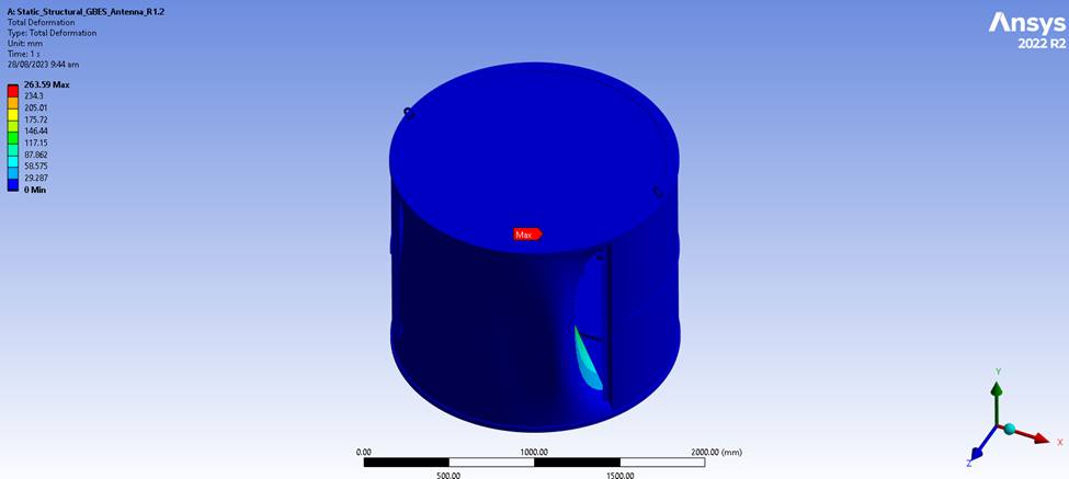
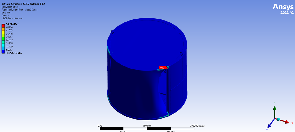
Want to check deformation & Von Mises Stresses
Results in case of First Approach:
Results in case of Second Approach:
-
August 28, 2023 at 12:12 pm
M Usman
SubscriberPlease guide me about the difference in results on same problem
-
August 28, 2023 at 12:13 pm
M Usman
SubscriberWhy results are varying when problem is same, just approaches were changed
-
August 29, 2023 at 9:52 am
Sahil Sura
Ansys EmployeeHello M Usman,
As seen from the description you've mentioned, there are different models compared for the same analysis for the boundary conditions, one actual manufactured and simplified CAD.
Would you please ensure, the mesh is constant for critical parts (or parts of interest) in both analyses? Also, have you attained any mesh-independent solution for any of the analyses, as that might be a critical concern to ensure? As it may help understand stress singularities.
When we perform any analysis of an actual geometry, we tend to simplify the geometry first ensuring the physical intent is unharmed. i.e. a rib added for the stiffness in an actual geometry cannot be removed to simplify the geometry in CAD.
So would you please help me with what changes have you performed in the geometries? So it will be easy for us to properly assist you.
Please check if the following video serves your purpose in identifying which details to include-
Identifying Geometry and Details to Include in a Simulation - Lesson 1 - ANSYS Innovation CoursesHope this helps!
Thanks,
Sahil
For more exciting courses and certifications, hit this link: Ansys Innovation Courses | Ansys Innovation Space
If you are not able to open the links, refer to this forum discussion: How to access the ANSYS Online Help
Guidelines for Posting on Ansys Learning Forum
-
August 29, 2023 at 10:53 am
-
August 30, 2023 at 8:11 am
Sahil Sura
Ansys EmployeeHi M Usman,
Thank you for sharing the designs. Now if you observe both the geometries are structurally quite different and structurally is not topologically but as per the structural function.
I'll refer to the violet geometry as Model A and the gray one as Model B just to avoid any confusion. So if observed in Model A, there are no columns or the transverse members as observed in Model B. These members will definitely add extra stiffness to the geometry.
I'll be happy to assist you with further queries but, if noticed the two comparison bodies are structurally different in the critical aspects, so they're bound to provide different results.
Thus it would be a good practice to get the results for the manufacturing design rather than the conceptual design, the design can be further optimized on various parameters to use the FEA to get a better and more efficient design.
You can use the approach of beams or slender bodies as observed in the geometry as per the requirement to get a better and more efficient FEA model for Model B.Hope this helps!
Thanks,
Sahil
For more exciting courses and certifications, hit this link: Ansys Innovation Courses | Ansys Innovation Space
If you are not able to open the links, refer to this forum discussion: How to access the ANSYS Online Help
Guidelines for Posting on Ansys Learning Forum
-
- The topic ‘Structural Analysis of Cylindrical Body under Wind Loads’ is closed to new replies.


-
4633
-
1535
-
1386
-
1225
-
1021

© 2025 Copyright ANSYS, Inc. All rights reserved.

