TAGGED: cfd, cooling-system, fluent, laminar-flow, nusselt-number, Wrong-results
-
-
August 20, 2023 at 12:01 pm
Alwan Hibatullah
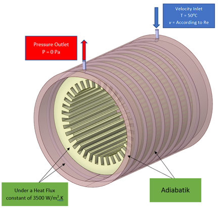
SubscriberI'm doing a simulation of an electric motor cooling system using Ansys Fluent. there are three components in my simulation, namely the stator, water cooling jacket, and helical coil as the fluid domain. I use a tetrahedral mesh in this simulation with y + = 1. for boundary conditions at the inlet is the inlet velocity and outlet is the outlet pressure, and in the stator section a constant heat flux of 3500 W/m2.K is given in laminar flow, or can be seen in the following picture of my geometry;when the simulation is finished running and I analyze the results, the Nusselt value that I get from the calculation does not match the validation equation from my journal reference. even though in my reference journal, the mesh elements used and y + used are the same and larger. however, when I simulate the helical coil alone without jacket and stator, the results I get are appropriate and correct. then when I move the mesh settings and helical coil setup to the intact cooling component, the results are still wrong.in addition I have tried to smooth the mesh and thicken the inflaction layer, but the results are still not appropriate. is my mesh still not smooth enough or is there a problem in other parts? please can anyone help my problem? -
August 21, 2023 at 11:02 am
Rob
Forum Moderator/forum/forums/topic/simulation-results-do-not-match-the-validation-equation/
-
August 21, 2023 at 11:03 am
Rob
Forum ModeratorDo the fluxes agree between the two models? What boundary conditions have you used?
-
August 21, 2023 at 11:17 am
Alwan Hibatullah
SubscriberHello Rob, thanks for reply
yeah. For the heat flux on the helical coil, I took the value when simulating the electric motorbike cooling system, so that it can be used as the temperature value on the wall and outlet as it should be, for the helical coil.then what does the boundary condition mean, what do I use?
-
-
August 21, 2023 at 11:41 am
Alwan Hibatullah
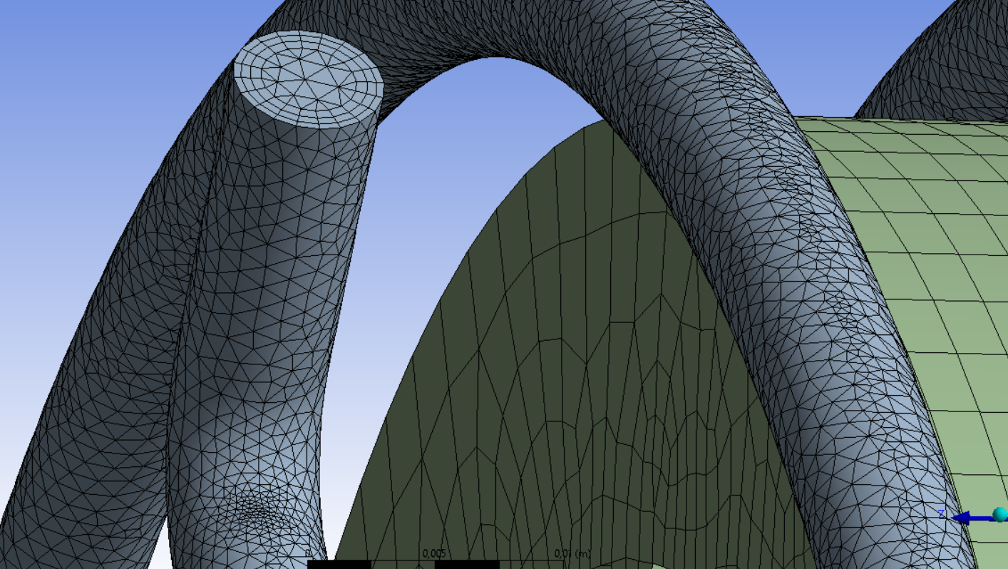
Subscriberand for meshing on the helical coil section it has the size as shown in the picture. with y+ = 1 at Re 500 with 6 mm hydraulic diameter
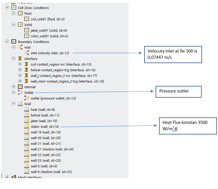
then for the boundary conditions as I mentioned using velocity inlet, outlet pressure, constant heat flux on the stator, and adiabatic jacket walls. for a screen shot on fluent as shown below
-
August 21, 2023 at 12:45 pm
Rob
Forum ModeratorAnd how does the heat balance look over all of the walls? Why have you got so many contact regions?
-
August 21, 2023 at 3:39 pm
Alwan Hibatullah
SubscriberI don't know. when I use common meshing, the boundary condition will be like that. the interface part has another name such as coil-contact-region-src has another name which is wall-20 and so does the other interface.
But when I use fluent special meshing (fluent with meshing), the boundary condition naming becomes simpler, as in the following picture
although the results between the two boundary conditions are still the same. still not in accordance with validation. so is there an error in the boundary conditions or in other parts?
-
August 21, 2023 at 3:42 pm
Rob
Forum ModeratorAssuming heat going in is the same as heat coming out and residuals are good then the model is likely correct. Whether the boundary conditions you set are appropriate is a different question, and one I can't easily answer.
The model with the conformal mesh is the one I'd focus on. How does the heat flux in the full model compare for each surface to the simple model?
-
August 21, 2023 at 3:58 pm
Alwan Hibatullah
SubscriberThere should be no problem with the boundary conditions, because the simulation I ran was just like any other simple simulation.
In the comparison of the full model and the simple model, I took the heat flux data received by the helical coil during the full model simulation. then I tried to simulate the simple model with the heat flux data. so you could say that in the full model and the simple model, the helical coil has approximately the same heat flux, so the temperature at the coil wall and outlet between the two models should have approximately the same value.
Then what other parts should I pay attention to besides the meshing?
-
August 21, 2023 at 4:06 pm
Rob
Forum ModeratorDid you take the heat flux as an average value or the heat flux (or temperature) profile?
Meshing should be about right, if the resolution isn't quite there you may see a few % difference. I'd then focus on the Nusselt Number definition to make sure you're using the correct reference values.
-
August 21, 2023 at 4:17 pm
Alwan Hibatullah
Subscriberi use the average heat flux value along the wall of the helical coil
then for the Nusselt value, as validation I use the Manlapaz and Churchill correlation equations for helical coils in laminar flow. for example, for Re 500 the Nusselt number should be around 12, and for simple models the Nusselt number should be correct with an error below 10%. but for the full model, the value of the Nusselt number that I get ranges from 2, so it has a high error.
for the record I did the analysis using excel, so when changing the model, I only changed the temperature values on the walls and outlets, so there shouldn't be any errors in the analysis calculations
-
August 22, 2023 at 7:19 am
Rob
Forum ModeratorDid you use the Nusselt Number value from Fluent, or take identical data to the correlation?
-
August 22, 2023 at 7:30 am
Alwan Hibatullah
SubscriberI took identical data from the analyzes using inlet, wall, and outlet temperatures. which I then compared with the correlation equation
if I take Nusselt number data from fluent, the value is very high, which is above 100
-
August 22, 2023 at 8:20 am
Rob
Forum ModeratorThe built in Nusselt Number uses a reference value - it can be negative too.
Check which wall temperature you used: the "normal" one plotted on the wall may not be what you're after.
-
August 22, 2023 at 8:36 am
Alwan Hibatullah
SubscriberI've tried using a reference value, but the result is the same. Or maybe there is something wrong in entering the value? because to be honest I'm still a bit foreign to reference values
then for the wall temperature you mean which one should I take?
because after I compared the full model with the simple model, both have more or less the same outlet temperature, but have very different wall temperatures -
August 22, 2023 at 9:23 am
Rob
Forum ModeratorHave a look at the definitions, you then need to pick whatever matches what you're comparing with.
-
August 22, 2023 at 9:41 am
Alwan Hibatullah
Subscriberdefinition in the boundary condition section? or where do you mean
I took temperature data on the wal helical tube, both the full model and the simple model. but on the full model the temperature of the wall helical tube is much higher. or is there a specific way for data retrieval on walls that are attached to each other?
-
August 22, 2023 at 10:17 am
Rob
Forum ModeratorField variables, https://ansyshelp.ansys.com/account/Secured?returnurl=/Views/Secured/corp/v232/en/flu_ug/flu_ug_FlowVariableDefs.html but also have a look at where (and what) you're adding on the thermal bc. Also, where it's going.
A heat flux boundary will adjust facet temperature to enforce the flux, temperature will adjust the flux. So, with flux it's possible to get very high (or low) temperatures depending on the flow field: with temperature the flux can be non-physical.
-
August 22, 2023 at 11:12 am
Alwan Hibatullah
Subscriberwhere is the destination of the link? because it takes an account number but I use ansys sutdent
so if I give a constant flux to the stator (see picture above), where will the heat flux propagate to the helical coil right? so that the helical coil will also be exposed to a constant flux with a greater value than the stator because of its smaller surface. then with the same heat flux, why is the temperature value of the helical coil in the full model and the simple model different between the two modes?
-
August 22, 2023 at 11:21 am
Rob
Forum ModeratorClick on Help in Fluent & paste the link into the browser that opens.
You're adding W/m2 as a flux. If you have a difference in surface area that can cause a slight error, the other issue is uniformity of the flux.
-
August 22, 2023 at 11:45 am
Alwan Hibatullah
Subscriberthen paste where? because I still enter the registration form
the meaning of this flux uniformity is that the flux in the stator and helical coil must have the same value?
-
August 22, 2023 at 12:13 pm
Rob
Forum ModeratorClick on Help in Fluent. That should open a web browser. In a tab in that browser paste the link I provided. Assuming you don't default to private/incognito that should take you to where I was linking.
-
August 22, 2023 at 12:36 pm
Alwan Hibatullah
Subscriberoh yes it can. but i'm sorry, I still don't understand what you mean or what you want to show me when I open the link. what does it have to do with the temperature on my helical coil wall which is still wrong
-
August 22, 2023 at 1:28 pm
Rob
Forum ModeratorYou asked about the wall temperature - there are several.
-
August 22, 2023 at 2:16 pm
Alwan Hibatullah
Subscriberoh yeah i got it. but I have tried all the variables for wall temperature like Wall Temperature, Wall Temperature (Thin), Wall Adjacent Temperature, static temperature, and total temperature, but they all have the same result
-
August 22, 2023 at 2:26 pm
Rob
Forum ModeratorThen there's likely something not being accounted for in the model set up.
-
August 22, 2023 at 3:14 pm
Alwan Hibatullah
Subscriberusually what is missed when preparing a model for a cooling system case like this?
-
August 22, 2023 at 3:40 pm
Rob
Forum ModeratorUsually it's a boundary setting or reporting issue.
Sketch out the layers of boundaries (hot bit, casing coil etc) as a list & link where the two models are common. Check what thermal load is then applied: ie W/m3/s or W/m2 etc and then look to see if the flux in the model ties up with what you expect. For a steady system Watt (I like bad puns) goes in must come out, so also check where heat leaves the system.
-
August 22, 2023 at 4:23 pm
Alwan Hibatullah
SubscriberI'm sure that the heat load uses W/m2.K and how to make sure the heat entering is the same as leaving, is it by selecting all the boundary conditions and calculating the heat?
-
August 23, 2023 at 8:02 am
Rob
Forum ModeratorYes, heat in, and heat out. But where you have a face common to both models check they're the same.
-
August 23, 2023 at 11:48 am
Alwan Hibatullah
Subscriberyes there is no problem when I check through the mass balance
then there are those who say that it is the relationship or interaction from solid to fluid that is problematic. what does that mean and how to check and fix it
-
August 23, 2023 at 1:09 pm
Rob
Forum ModeratorFluid-solid thermal tends to be an issue when the mesh is too coarse.
-
August 23, 2023 at 1:56 pm
Alwan Hibatullah
Subscriberthis means having to fine-tune the meshing on the interconnected parts of the wall?
-
August 23, 2023 at 2:07 pm
Rob
Forum ModeratorNot normally, if you use inflation and think about mesh resolution it's usually pretty hard to get the solution badly wrong.
-
August 23, 2023 at 2:44 pm
Alwan Hibatullah
Subscriberhere I use a fairly small mesh size in the fluid domain and have tried using quite a lot of inflation layers with y+ = 1, but the results are still not right. however, for the mesh in the solid domain, I still have quite rough settings, and not as small as in the fluid domain.
ah for the record, in my reference journal they use y+ = 5, with a maximum element mesh of 5 million. I've matched them as closely as possible to my references, though I don't know how small their smallest mesh is in the solid domain.
-
August 23, 2023 at 3:06 pm
Rob
Forum ModeratorA few % error may be down to a marginal difference in mesh. A much larger difference is more likely down to a setting: be that boundary condition or geometry dimension.
-
August 23, 2023 at 3:37 pm
Alwan Hibatullah
SubscriberI've seen several video tutorials on YouTube that have similar cases, but the fluent setup settings that I see are not too different from mine
Is there another tutorial that has similarities so that it can be used as a reference? because I haven't found anything really similar, like a fluid that functions as a coolant for the solid domain with a heat flux heat source
-
August 23, 2023 at 4:12 pm
Rob
Forum ModeratorI don't think so, all the tutorials I can point you at at in Fluent's Help system or Learning on here. Have you compared all of the common faces in each model to see where differences come in?
-
August 23, 2023 at 6:40 pm
Alwan Hibatullah
Subscriberyes it has, and I haven't found a model at least similar to mine. most of those using helical coils are heat exchangers with two fluids, and unlike mine which is a transfer of heat from solid to fluid
-
- The topic ‘simulation results do not match journal references’ is closed to new replies.


- JACOBI Convergence Issue in ANSYS AQWA
- Is it able to solve turbomachinery using density-based solver in Fluent?
- Two-way FSI simulation
- Ensight Force_per_unit area_EV
- RIBBON WINDOW DISAPPEARED
- Fluent Meshing Error when .dsco not .stp
- Ansys Fluent for modelling Ocean Wave reactions to Wave Barriers
- Battery Pack cooling
- ISAT ABORT error
- UNASSIGNED INTERFACE ZONE DETECTED FOR INTERFACE…

-
4592
-
1494
-
1386
-
1209
-
1021

© 2025 Copyright ANSYS, Inc. All rights reserved.


