-
-
August 9, 2018 at 11:00 pm
Walaa
SubscriberWhen I am calculating, the calculation stopped and this message occurred "floating point exception', what does that mean ?Â
-
August 10, 2018 at 12:55 am
Karthik Remella
AdministratorHello Walaa,
Could you please check the quality of your mesh? Max skewness and min orthogonal quality?
Thank you.
Best Regards,
Karthik
-
August 10, 2018 at 5:34 am
DrAmine
Ansys EmployeeThat means divergence in the linear solver. This might happen even within the linearization step. We need to know some more information about your model and as Kremella said your mesh metrics.Â
-
August 17, 2018 at 11:50 am
Walaa
SubscriberI will check the mesh again and let you know what happened. Thanks
-
August 17, 2018 at 12:17 pm
DrAmine
Ansys EmployeeYou are welcome Walaa!
-
August 24, 2018 at 12:59 pm
Walaa
SubscriberI am using ANSYS 19,
the mesh quality as the following:
mesh Quality:
Â
Minimum Orthogonal Quality = 4.55661e-01 cell 1198876 on zone 2 (ID: 1198877 on partition: 0) at location (-1.92211e+00 4.59320e-01 9.80769e-03)
(To improve Orthogonal quality , use "Inverse Orthogonal Quality" in Fluent Meshing,
where Inverse Orthogonal Quality = 1 - Orthogonal Quality)
Â
Maximum Aspect Ratio = 1.40133e+02 cell 1845 on zone 2 (ID: 1846 on partition: 0) at location (-2.32400e+00 9.13900e-01 5.00192e-01)
-
August 24, 2018 at 1:30 pm
-
August 24, 2018 at 1:31 pm
-
August 24, 2018 at 1:33 pm
-
August 24, 2018 at 1:34 pm
-
August 24, 2018 at 1:34 pm
-
August 24, 2018 at 1:35 pm
-
August 24, 2018 at 1:36 pm
-
August 24, 2018 at 1:44 pm
-
August 24, 2018 at 1:47 pm
-
August 24, 2018 at 1:48 pm
-
August 24, 2018 at 3:24 pm
Rob
Forum ModeratorThanks, looks like you've thought this through properly. Doing this for all models while you're learning is a really good idea, including once you've left University.Â
I assume you have 10-15 cells through the depth of water, and some refinement around the free surface.Â
Check that you've got enough space above the water level to account for ripples etc. Setting turbulence intensity at 5% may be a bit high, typically 2-3% is suitable for most flow rates.
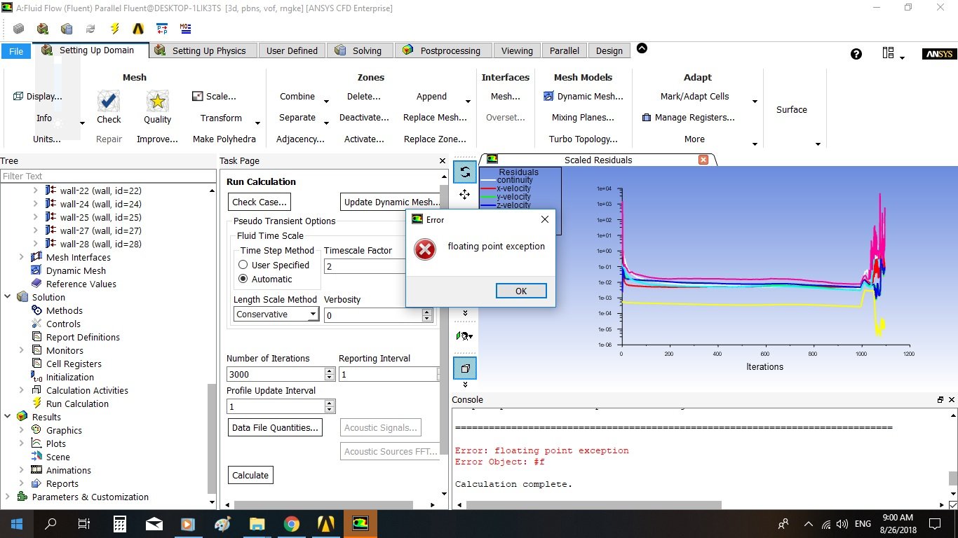
I would also suggest reducing the timescale factor by a couple of orders of magnitude, or trying a transient solution.Â
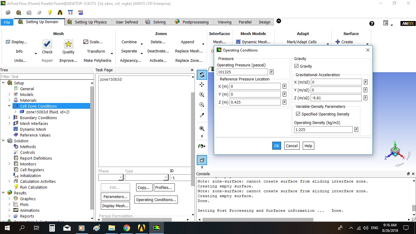
Finally, how have you initialised the solution?Â
-
August 24, 2018 at 4:03 pm
-
August 24, 2018 at 4:52 pm
Rob
Forum ModeratorLooks about right. Plot some contours of water level on the side walls & channel centre lines to see what the initialisation process gives: ie is it sensible.Â
Â
-
August 25, 2018 at 6:34 am
DrAmine
Ansys EmployeeCan you post a pic straight after initialization and tell us how you defined all the inflow and outflow bcs (all 3)?
-
August 25, 2018 at 12:45 pm
Walaa
Subscribermmm, I don't know how
-
August 25, 2018 at 2:42 pm
Karthik Remella
AdministratorHello,
You could plot contours of volume fraction showing walls to highlight the level of liquid along the walls.
You can also create a clip plane (z - plane) in the middle (along the axis of your pipe) and plot the volume fraction contours on this plane. This will highlight the level of liquid at the center if the pipe.
About the BCs, maybe share screenshots of your boundary condition panels?
I hope this helps.
Best Regards,
Karthik
-
August 26, 2018 at 7:18 am
-
August 26, 2018 at 7:20 am
-
August 26, 2018 at 4:34 pm
Karthik Remella
AdministratorHello,
It is possible that there might be an issue with your problem formulation. Please share screenshots of your boundary condition set-up in Fluent?
I'd strongly recommend that you create monitors and assess your simulations. Perhaps, one of them might explain your floating point error.
You might also want to share your initial set-up case file here. Someone who is not an ANSYS employee might have a look and tell you why you are seeing this issue.
I hope this helps.
Best Regards,
Karthik
-
- The topic ‘Problem during calculation’ is closed to new replies.
-
6104
-
1906
-
1436
-
1308
-
1021
© 2026 Copyright ANSYS, Inc. All rights reserved.


