TAGGED: 2D, cfd, fluent, mesh, supersonic, Supersonic-Nozzle-Flow
-
-
August 4, 2023 at 12:47 pm
felice_lucivero
SubscriberHello everybody,
I am trying to simulate a 2D supersonic inlet and analyze the effect of the imposition of a certain back-pressure ratio between the inlet and the outlet.
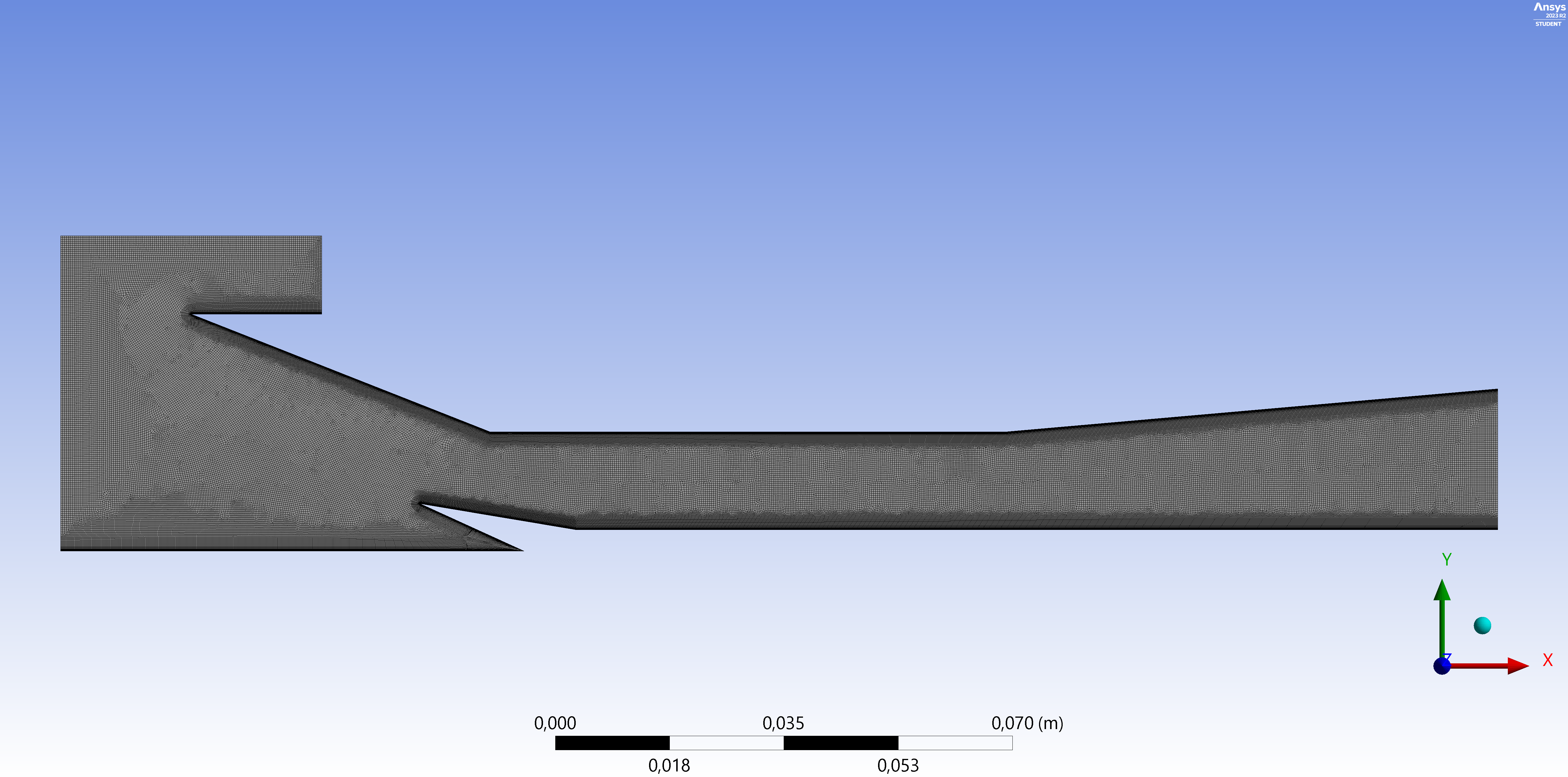
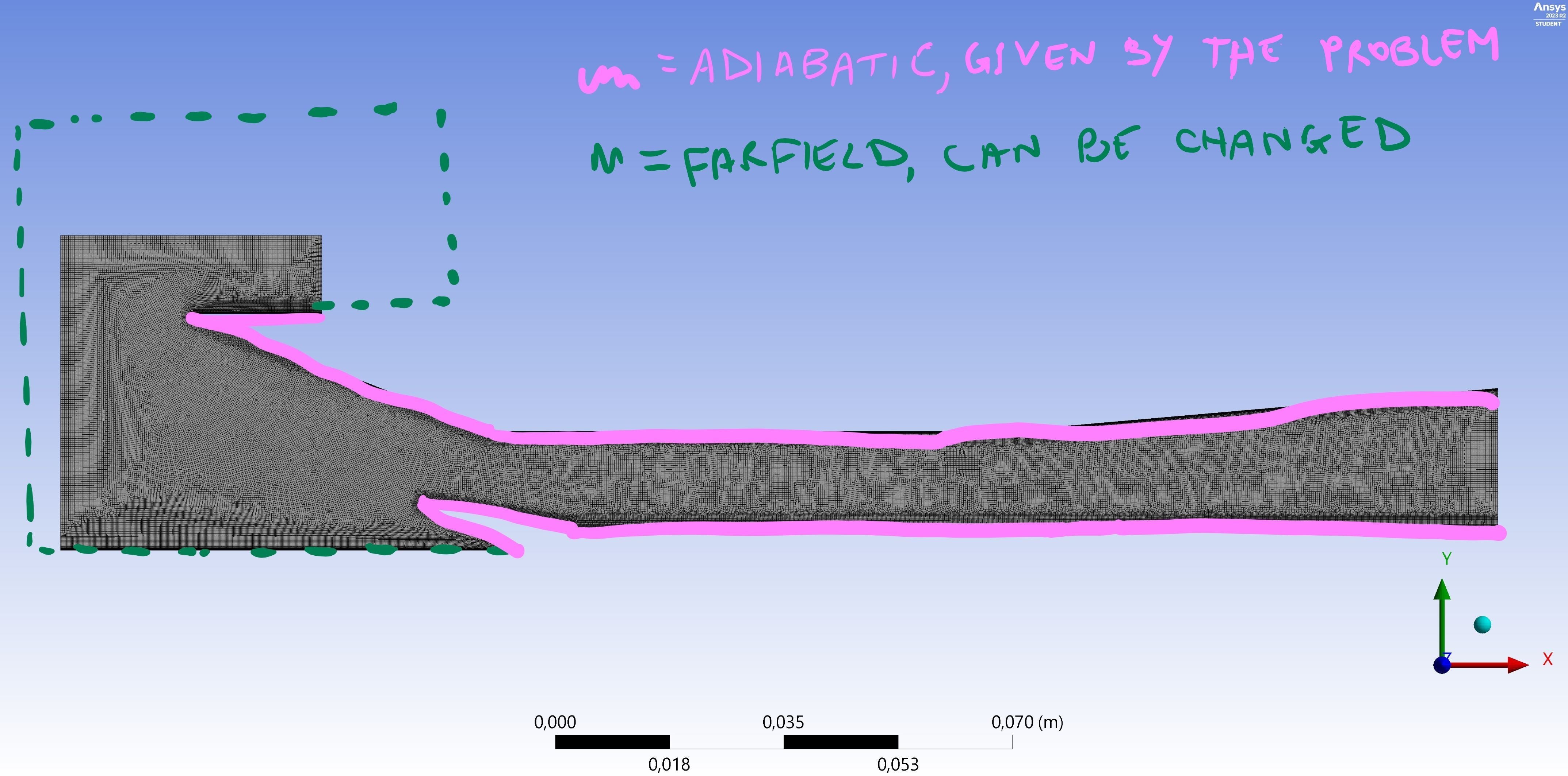
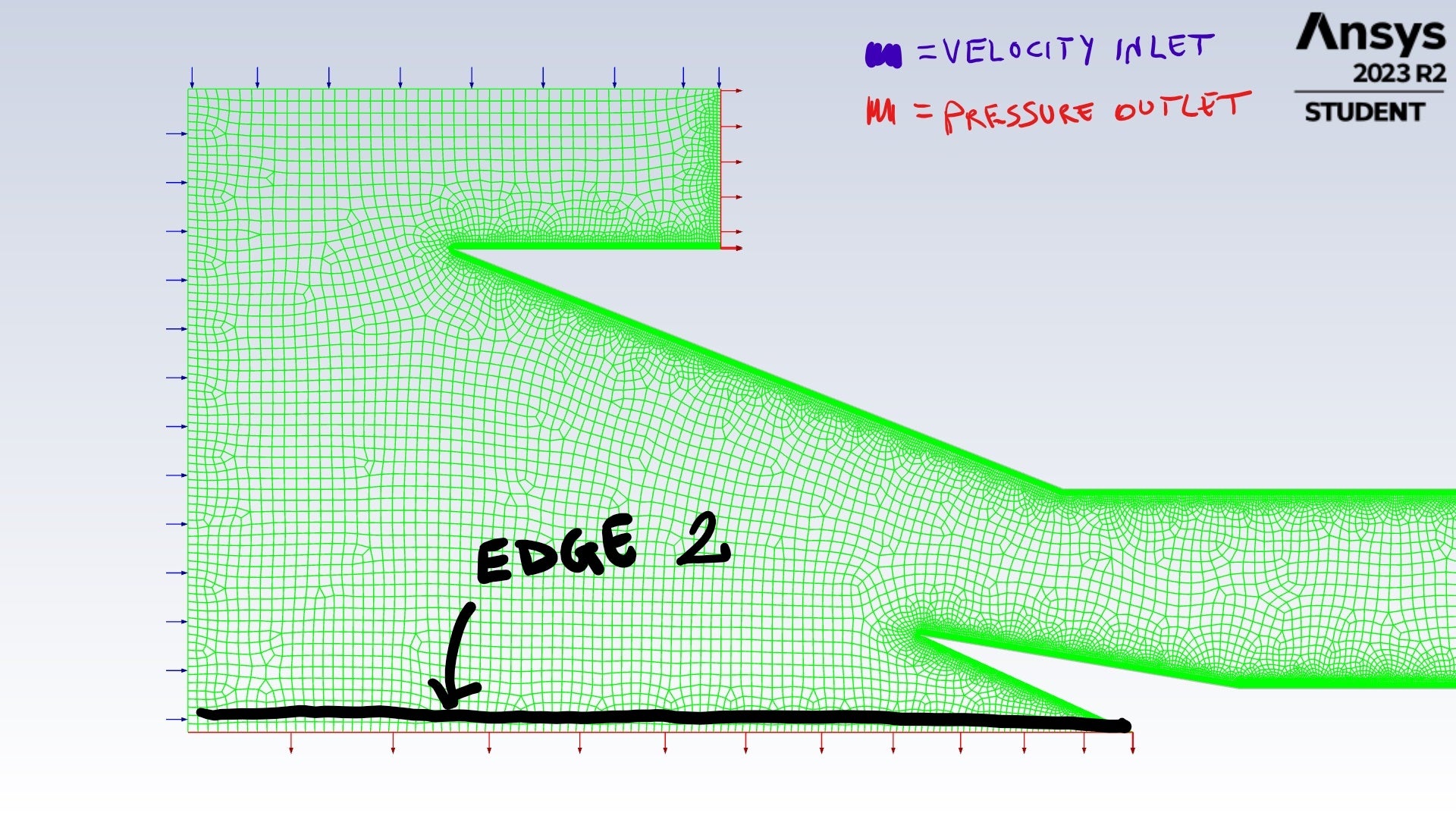
Here is the geometry and mesh I am simulating:
The inlet section is on the left and the outlet section is on the right.
I would like to obtain a full structured mesh, even though this was the best result I was able to get to. I have used either the number of divisions' option, for each and every edge of the geometry, and the inflation option. The wall y+ was in between 0.0014 and 5.
Any suggestion about how to improve the mesh quality would be really welcome.
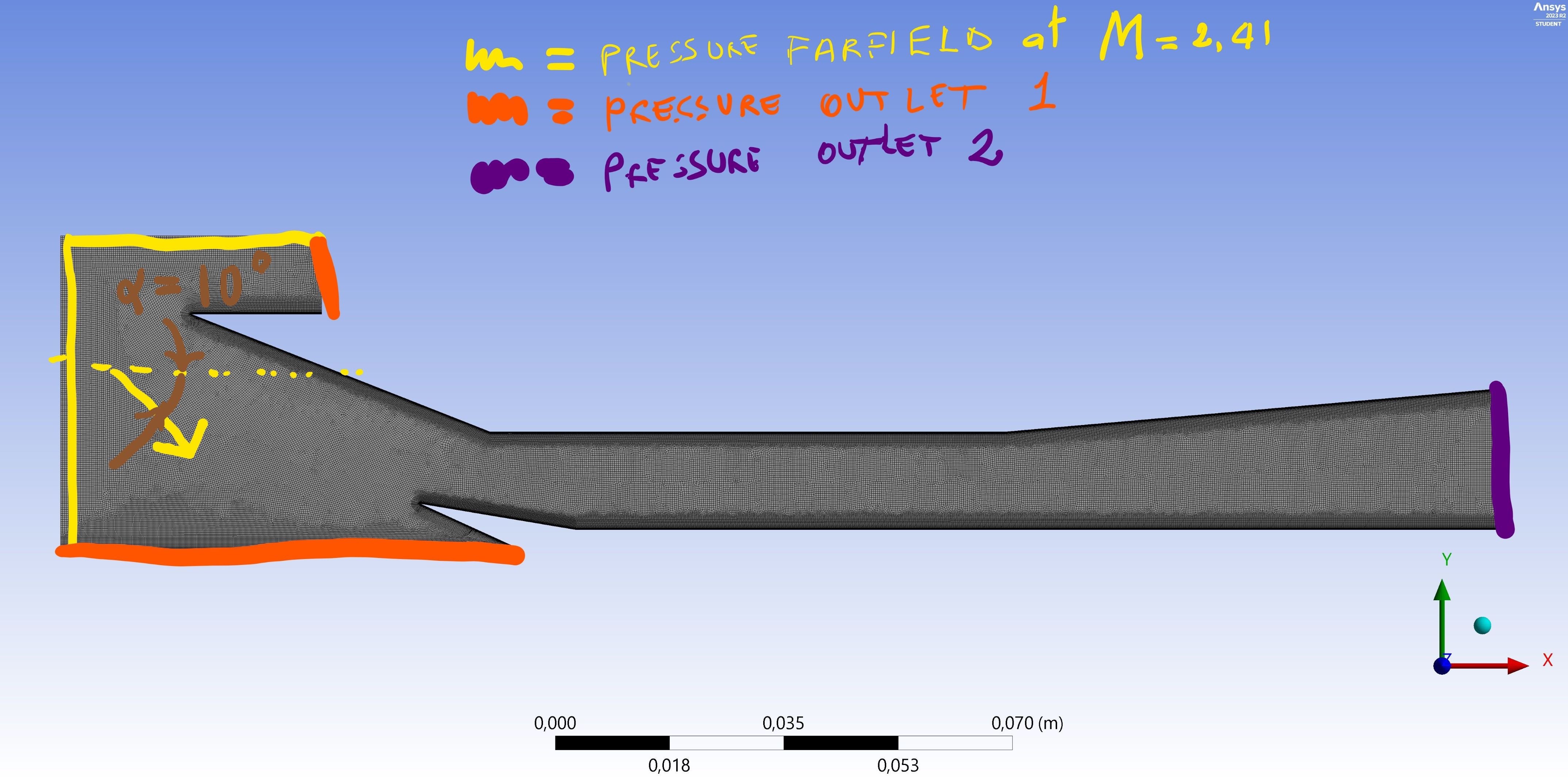
Then I moved to Fluent and I ended up with results that are not that good. Here are the boundary conditions I imposed:
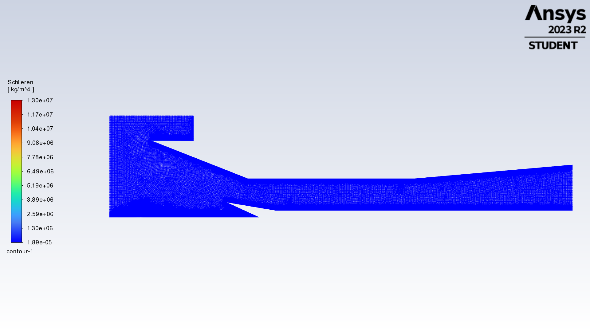
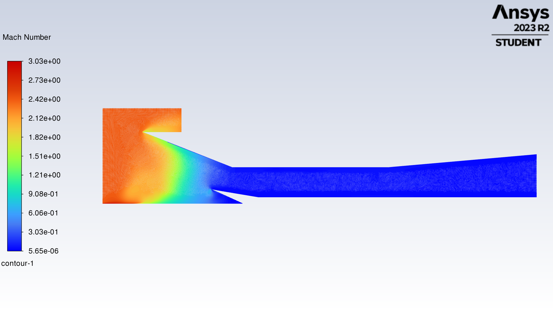
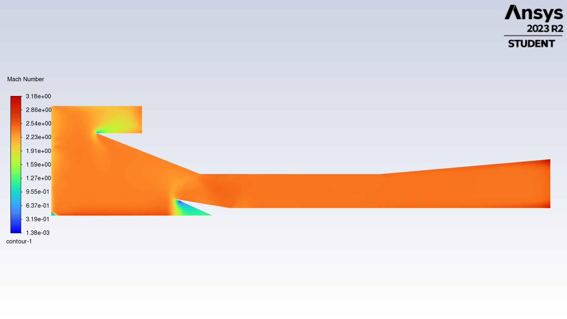
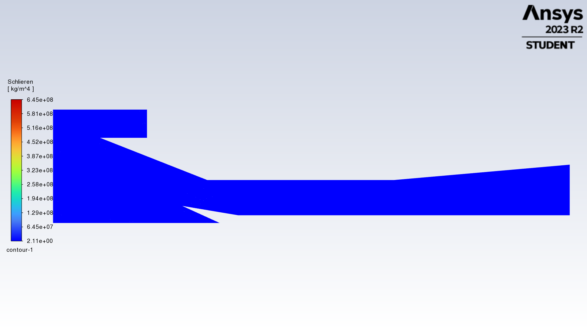
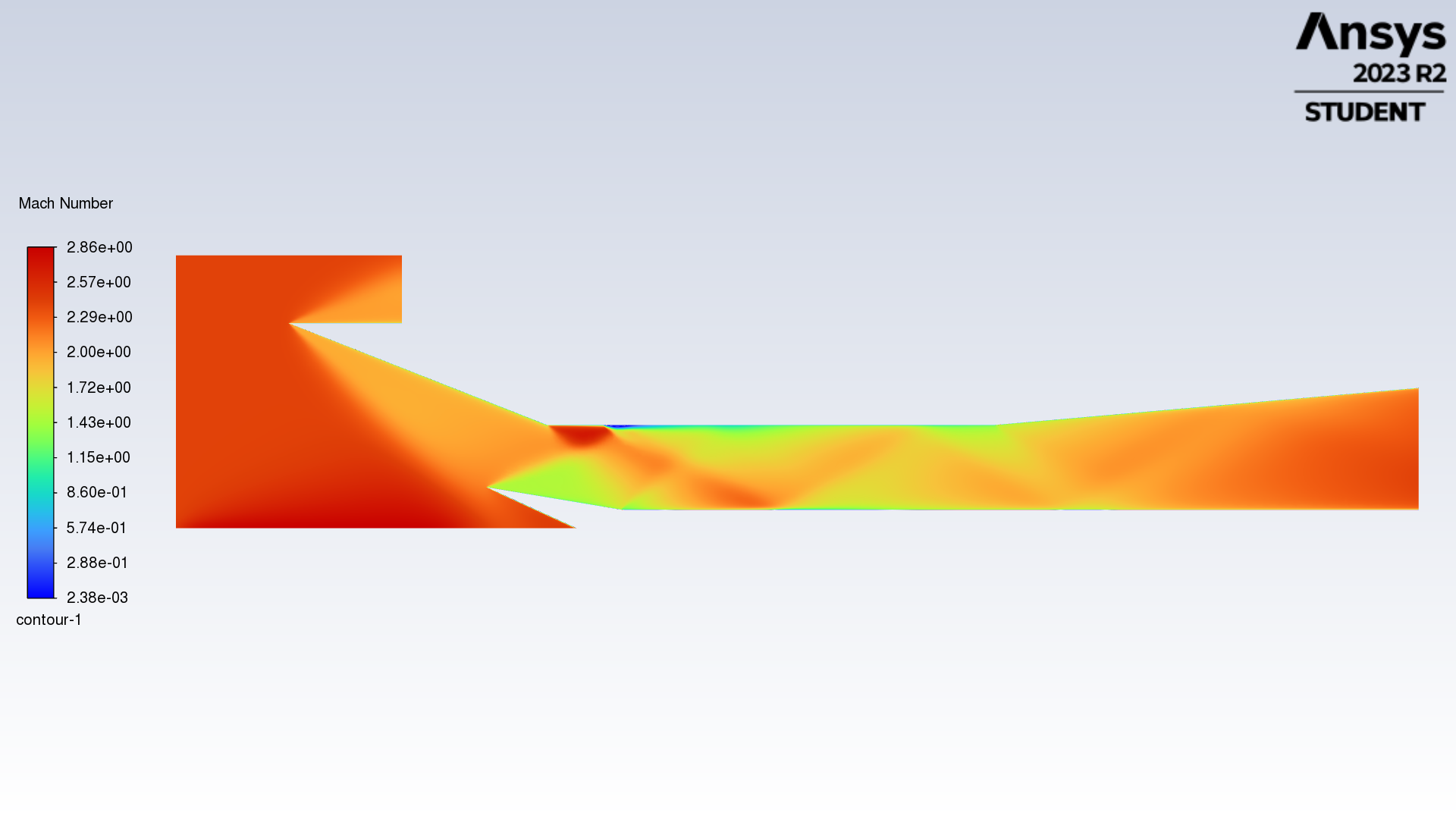
Unfortunately there is no shockwave generated in the channel. As you can see in the schlieren and Mach contours:
The back-pressure ratio (the ration between the back pressure outlet and the inlet pressure) is 0 in this case.
There should be a very clear shockwave pattern in the channel, do you have any idea why I am getting it wrong? What adjustements can I introduce?
-
August 4, 2023 at 2:02 pm
Federico
Ansys EmployeeYour mesh looks fine (y+ of 0.0015 is perhaps even overkill), I believe the issue lies in the boundary conditions.
How did you decide on the geometry of your domain? I'm not sure I understand Pressure outlet 1. The Pressure farfield BC should be used far enough from the object of your simulation.
-
August 4, 2023 at 2:47 pm
felice_lucivero
SubscriberThank you for replying Federico.
I am trying to replicate the reuslts reported in a scientific paper, so the geometry of the channel sticks to that.
In reality, in the paper are not reported precise dimensions about the farfield, so I chose those by myself. Probably it will be more clear in this pic:
So you are suggesting to increase the size of the farfield?
I set pressure outlet 1 as a pressure outlet with half of the pressure I imposed for the pressure farfield bc. I did this since the flow coming from the pressure farfield is tilted of -10[deg], so in order to avoid the flow to be accumuleted I set pressure outlet as bc for those two edges.
For pressure outlet 2, here is where I set the back-pressure, zero for this specific case.
Finally, something I forgot in the previous post is that when I computed the solution in Fluent, I also got this message: “Reversed flow on 1 face (0.2% area) of pressure-outlet 10”.
I hope to hearing from you soon.
-
-
August 4, 2023 at 7:12 pm
Federico
Ansys EmployeeThe far-field boundary condition is particularly useful when modeling external flows, where the flow behavior at the boundaries is not directly influential on the region of interest. Hence, I would not recommend for this case.
The boundary conditions should be listed in the paper. Perhaps that can give some guidance.
What you are looking to do is similar to this: Supersonic Waves Reflection in a Duct | Ansys Courses.
With that in mind, try and think about how you can reconstruct your domain and assign correct boundary conditions.
-
August 7, 2023 at 12:21 pm
felice_lucivero
SubscriberDear Federico,
The boundary conditions I mentioned before, in my first post, are actually those listed in the paper. Unfortunately, this is not working since I ended up with the contours' plot I attached, without any shockwave pattern captured.
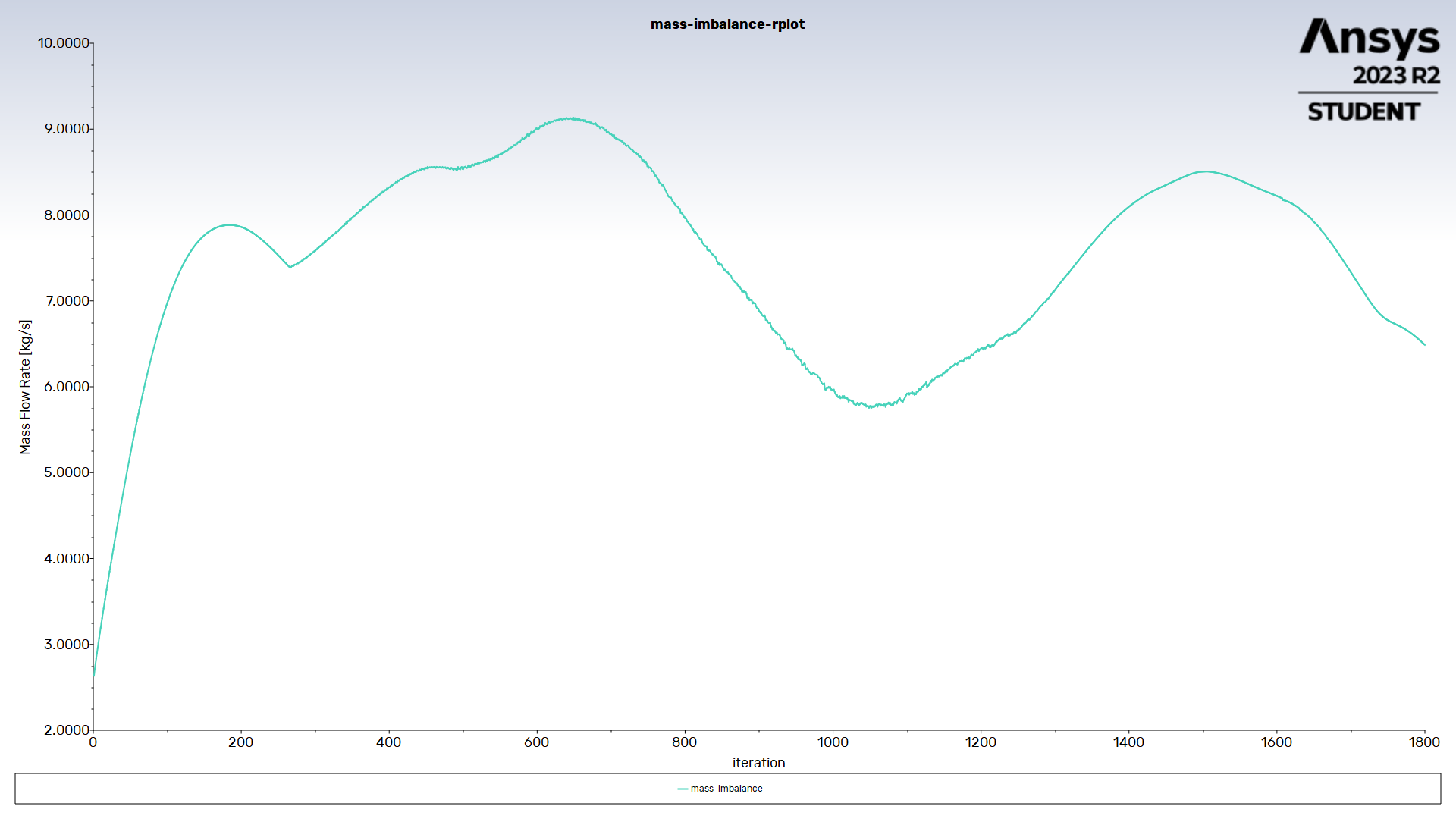
For this latter case, I also monitored the mass imbalance (difference between the mass inflow and outflow) and this turned to settle around 160 [kg/s], that makes no sense since it should be around zero.
After that, I tried to replicate the very same procedure described in the video you suggested.
In this case I got the following contours:
Still, these results are not that good, besides the fact that the mass imbalance in this case settled around -150 [kg/s]. Just to let you know, I also introduced an automatic mesh adaption, as suggested in the video you shared.
Moreover, in both of these simulations I got the message about the "reversed flow", that make me think about a possible error in the mesh grid.
I hope to hearing from you soon,
Thank you
-
August 7, 2023 at 12:47 pm
Federico
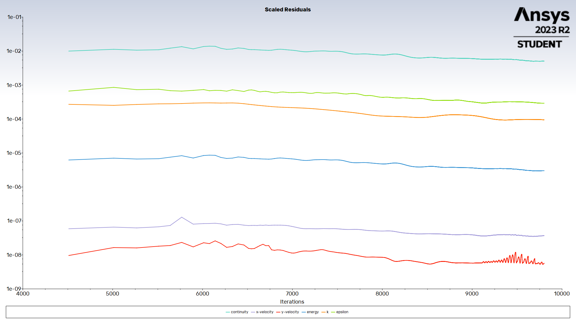
Ansys EmployeeAre you selecting all inlet/outlet boundaries to compute the mass balance? If so, your results indicate to me that your solution has not converged. Note that mass may exit your domain from each pressure outlet boundaries. What do your residuals look like?
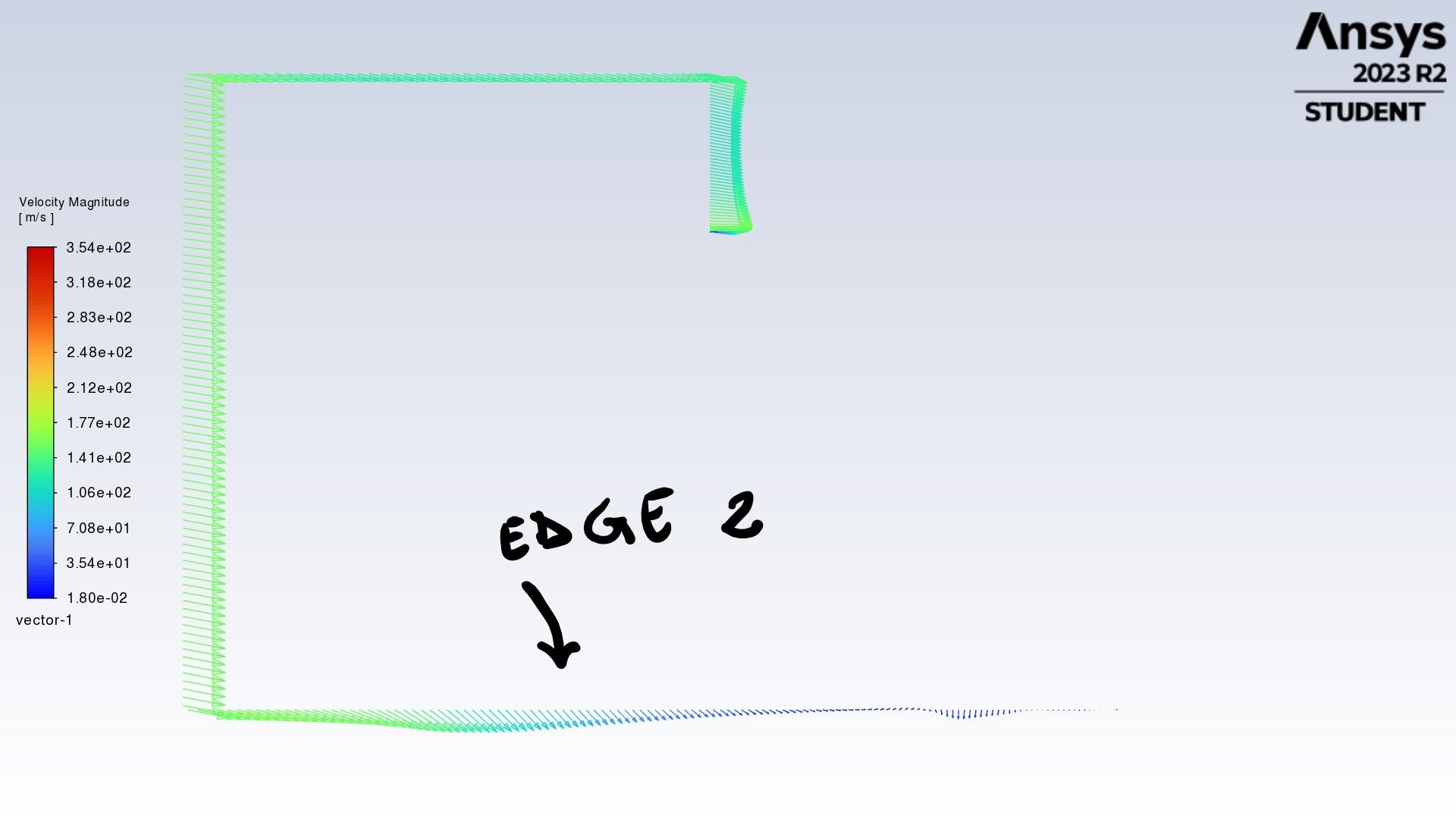
Regarding reversed flow, the warning message should indicate where this occurs (which surface). You can also plot vector velocity to inspect this.
I would suggest aiming to get the the flow you are looking for qualitatively first. Turn off automatic mesh adaption for now.
-
August 7, 2023 at 3:31 pm
felice_lucivero
SubscriberYes, I am selecting all inlet/ outlet boundaries. Here is the residual plot:
Do you suggest to keep on iterating?
I actually tried to modify the mesh grid in order to avoid reversed flow, but this latter is still pulling up. May it be a good choice to check the "Prevent reversed flow" slot when I set the outlet bc?
I deactivated mesh adaption.
-
August 7, 2023 at 3:43 pm
Federico
Ansys EmployeeYes, you should definitely keep iterating, it seems like the solution is just starting to improve a bit (decreasing residuals). Continuity for example is still at about 10e-1. A good rule of thumb is to have 10e-3. I am still curious that your mass imbalance is still so far off.
Regarding the reversed flow, where is this occurring? The console should identify the surface. If you create a velocity vector plot, you will see where/why this is happening.
-
August 7, 2023 at 4:25 pm
felice_lucivero
Subscriber -
August 7, 2023 at 7:27 pm
Federico
Ansys EmployeeThese results that you are showing have not converged. For steady-state calculations, any monitor that you observe, for example the mass imbalance as you are showing here, should stabilize around a constant value.
You definitely need to run this longer. If the residuals do not decrease, then you should consider reviewing the solver settings.
I wouldn't worry too much about the reversed flow for now, until you actually get a converged solution.
-
August 8, 2023 at 9:41 am
-
August 8, 2023 at 1:12 pm
Federico
Ansys EmployeeUnfortunately, it seems like your solution is not improving. This may be due to:
1) bad mesh quality. From the figures, your mesh seems ok to me, but it might be worth checking. What is your mesh quality? in terms of cell skewness;
2) your solver settings are incorrect;
3) your boundary conditions are set incorrectly.
-
August 8, 2023 at 3:34 pm
felice_lucivero
SubscriberHello Federico,
I decided to went back to the initial setting of the problem, that means I imposed a pressure farfield boundary condition.
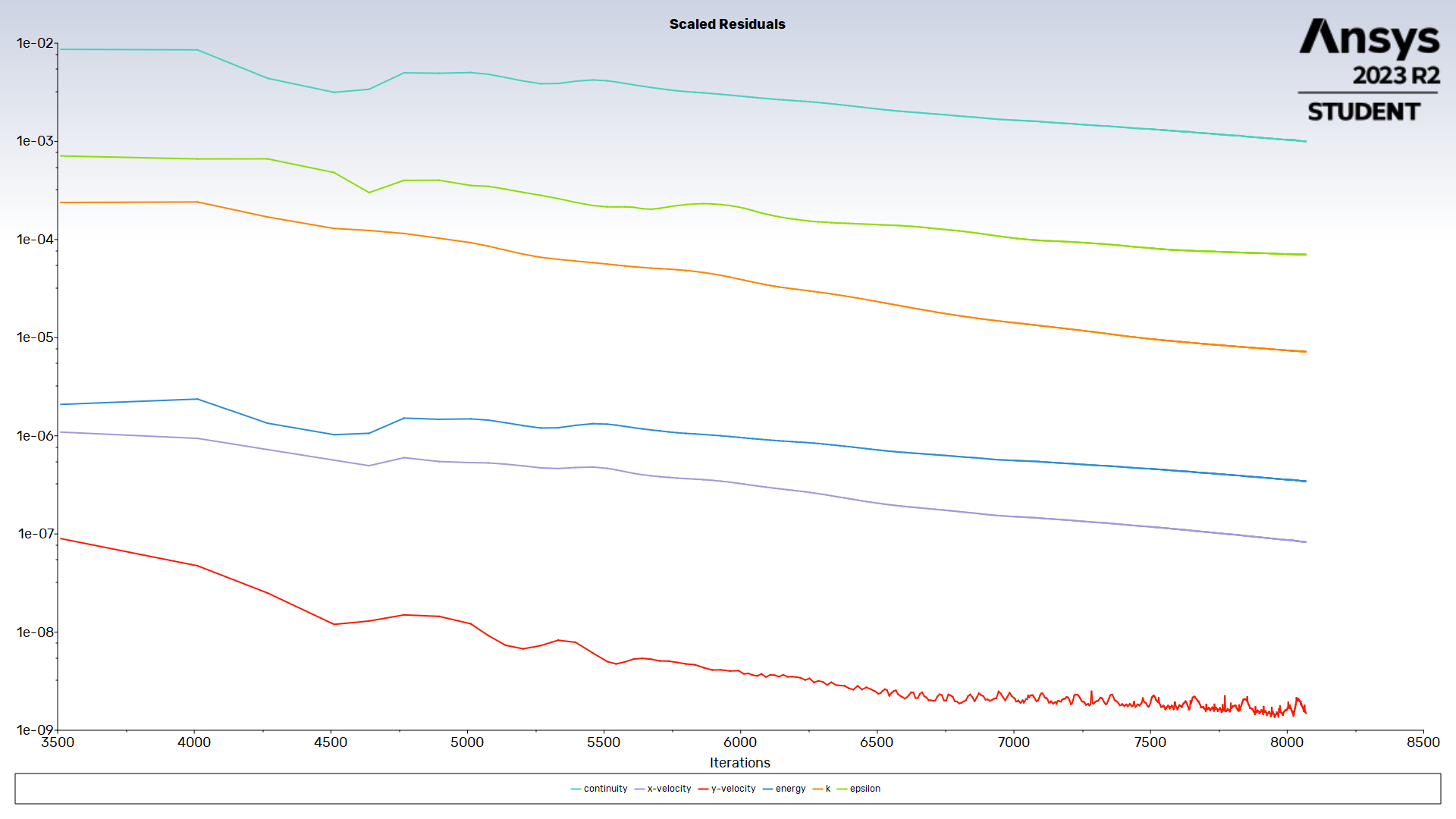
I let the simulation run for 10k iterations, but the process was stopped due to convergence at around 8k iterations.
Here are the residuals:
The mass imbalance was good as well, it settled around zero.
The Mach contours are looking good, with the shockwave pattern fully captured:
Nevertheless, the contour of Schlieren are basically empty:
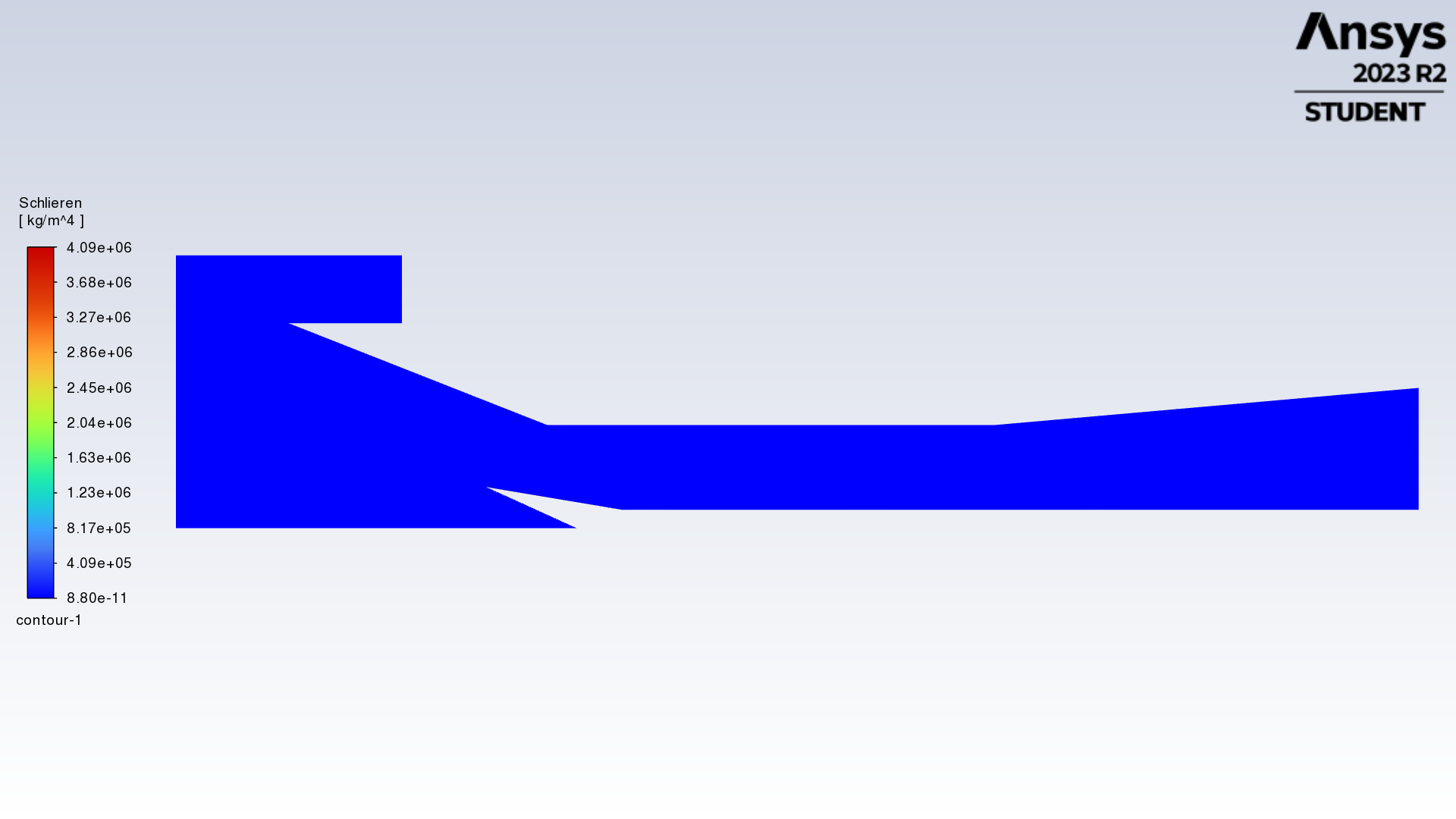 Why, in your opinion, is this happening?
 Just to let you know, the mesh quality in terms of cell skewness is between 1e-10 and 1 (this latter value is localized in correspondece of the cowl lip).
-
-
-
August 8, 2023 at 4:01 pm
Federico
Ansys EmployeeSeems like you are making progress!
The mesh quality is not ideal though, you would want maximum skewness to be no more than 0.7.
Regarding your Schlieren plot, if you look at the colorbar, you have a wide range of scales. I strongly suspect the skewed cells to be the culprit here, where you would get diverging values which skew the range of the solution for Schlieren. So again, go back to your mesh and see if you can improve on it.
You can still view your Schlieren results here. In the contour dialog box, uncheck the Auto-range box, and provide a lower value for the Max. Try 1 or 2 orders of magnitude beyond the minimum value, and change this until you get the contours that you expect.
-
September 8, 2023 at 10:34 am
felice_lucivero
SubscriberHello Federico,
sorry for the late response.
I tried what you said for the Schlieren contours and it actually worked.
When it comes to the mesh settings, I have already applied a sizing method for each and every edge of the geometry, I have also introduced an automatic method (quadrilateral dominant) and inflation (30 layers approximately).
What do you suggest in order to improve the mesh quality?
-
-
- The topic ‘2D Supersonic Inlet’ is closed to new replies.


-
4803
-
1582
-
1386
-
1242
-
1021

© 2026 Copyright ANSYS, Inc. All rights reserved.

