-
-
July 3, 2018 at 3:26 pm
cfd_learner
SubscriberHow to simulate an axial cooling fan to see pressure rise across it? My fan has pa dia of 300mm and confined inside a channel. The inlet of fan (channel inlet) is 20mm and fan outlet is 250mm (channel exit). What should be the appropriate BCs and domain extents? I only know rotational speed. My final target is to make fan performance map. Need guidance to solve the problem. I am working first time with turbomachines.
Regards -
July 4, 2018 at 2:51 am
Keyur Kanade
Ansys EmployeeHello,Â
Please look at following example.Â
https://www.youtube.com/watch?v=iAm2f7AHLfg&t=67s
https://www.youtube.com/watch?v=pn0J_XSOkds&t=86s
This is not exact example. But it will help you to build your model.Â
Â
Regards,
Keyur
Â
-
July 5, 2018 at 10:23 am
-
July 5, 2018 at 1:16 pm
Amine Ben Hadj Ali
Ansys EmployeeHi,
Â
The BC's outside will be those of your room. So if your room is closed then you would have only walls if you have some openings (like open window, or door) from where fluid might be extracted or expelled then assign the related faces a pressurized b.c.
Â
A.
-
July 7, 2018 at 9:08 pm
Raef.Kobeissi
SubscriberThe B.C should be outlet pressure.Â
-
July 13, 2018 at 1:15 am
cfd_learner
Subscriber@Raef.Kobeissi: The outlet pressure may produce "reverse pressure" at some faces. Will it be correct in that case?Â
- Is it necessary to model the room environment or only fan with the extended channel in both upstream and downstream sides will be enough?
- How to get the performance map for the fan?
- At which point I have to calculate "Fan Pressure", will it be static or total?
- How to compute total-total or static-static or total-static efficiency?Â
Kindly recommend some good literature or comment here. This is an automotive cooling fan.
-
July 19, 2018 at 10:00 pm
Karthik Remella
AdministratorHello cfd_learner,
You can have reversed flow on certain boundaries when you use 'outlet BC' and that is a perfectly acceptable solution. The fan tries to move air in a specific direction and if you are solving an incompressible flow model, there has to air flow coming into your computational domain. For a pressure outlet boundary condition, this would imply reversed flow.Â
There is a lot of material in open literature about turbulent exhaust fan models and on fan curves. Please refer to these material to understand the fan performance curves. Generally, these performance curves are plotted as static pressure against volumetric flow rate.
Please check out this excellent video tutorial created by Raef Kobeissi. It explains the model set-up and boundary conditions in detail. It also outlines the mesh details necessary for your simulation.
https://www.youtube.com/watch?v=KFrZoDWUC5s
Hope this helps.
Best Regards,
Karthik
-
August 5, 2018 at 9:31 am
cfd_learner
SubscriberI have simulated the fan by following the above posts. My computational domain and boundary conditions are sketched in the figure. the Pressure inlet and outlet are far from the fan approximately 50 times of the diameter of the fan in all directions. The pressure at the inlet and outlet is set as 0 relative to the atmosphere. However, the operating pressure in 101325Pa. I would like to know at which point I have to calculate the pressure and mass/volume flow rates to plot the fan performance. I tried to compute the area-average pressure at various planes along the channel/tube and shown below. The pressure is very small and negative. Is this correct?
What will be the rotation of fan in case of pushing or pulling the air and what will be the appropriate boundary conditions in either case?
Â
Â
Â
-
August 5, 2018 at 12:41 pm
Karthik Remella
AdministratorHello,
I have a few questions about your simulations.
- Are you using Mesh motion for your simulation (as shown in the one of the videos above)? What is the RPM you are using?
- Have you verified your mesh-interfaces?
- Are you running a steady state or a transient simulation?
You should set-up plots of mass-flow rate to monitor the behavior. When this value from your monitors become steady, that would be a good time to stop the analysis and switch over to post-processing.Â
Plotting velocity streamlines or velocity vectors would be one way to understand the rotation of your fan. Please refer to the above video for detailed instructions for streamlines plot
I hope this helps.
Thank you.
Best Regards,
Karthik
-
August 5, 2018 at 4:31 pm
cfd_learner
SubscriberDear Karthik.
The answers of your questions are:
- Are you using Mesh motion for your simulation (as shown in the one of the videos above)? What is the RPM you are using?
- Â Â I am using multiple reference frame (MRF) option of Fluent which is a stead-state approximation. Fan is running on 1500rpm CW from front side.
- Have you verified your mesh-interfaces?
- Â Â yes. interfaces are correct.
- Are you running a steady state or a transient simulation?
- Â Â steady-state simulations. Â Â
I want to plot efficiency. At what point in my solution domain I have to take pressure difference and volumetric flow rate?Â
Â
Regards
- Are you using Mesh motion for your simulation (as shown in the one of the videos above)? What is the RPM you are using?
-
August 5, 2018 at 4:36 pm
Karthik Remella
AdministratorHello,
Please create a surface / line monitor for static pressure and / or velocity as a function of iterations and make sure you are seeing a constant value. This should give you an indication when you have obtained a steady state solution. Once you obtain this, you should be set for post-processing.
I hope this helps.
Thanks.
Best Regards,
Karthik
-
August 5, 2018 at 5:01 pm
cfd_learner
SubscriberThe plot shown in my previous post/reply was taken after converged solution for various planes along the axial direction of channel/tube. The pressure value is negative and very low. I obtained volume flow rate at channel exit as 100 ft^3/min. At what location I need to calculate pressure difference? Since outlet and inlet are far-away from the fan and both set a zero pressure in simulation and I was also obtained zero pressure at inlet and outlet after converged solution.
Â
My main annoying concern is about efficiency which is calculate by the ratio of pressure difference multiplied by the volumetric flowrate and shaft power, i.e.
Efficiency = dP x Q / P_shaft ????? dP???
-
August 5, 2018 at 10:07 pm
Karthik Remella
AdministratorHello,
I'd suggest you take a cut-plane along the center of your channel (along the flow direction and not across) and plot static pressure and velocity contours. It might help you understand why your static pressure curve (earlier plot) is small. I'd also recommend checking you mass balance along your computation. This might give you an indication about your case. I hope this helps.
Thank you.
Best Regards,
KarthikÂ
-
August 6, 2018 at 12:53 pm
Raef.Kobeissi
SubscriberI wonder why is your fluid domain so large? that would require a lot of processing for a small fan.
Regards
-
August 6, 2018 at 2:13 pm
cfd_learner
SubscriberDear Raef Kobeissi,
Â
Will you suggest any appropriate domain size considering 220mm fan dia?Â
Â
Regards
-
November 3, 2019 at 4:29 pm
mhmt0zden
SubscriberHello,
I have been trying to solve the same problem you faced one year ago.Â
I generated mesh and set up BCs etc. as in the tutorial videos above.Â
I want to calcute efficiency of the fan using the equation you shared;
Efficiency = dPt x Q / P_shaft
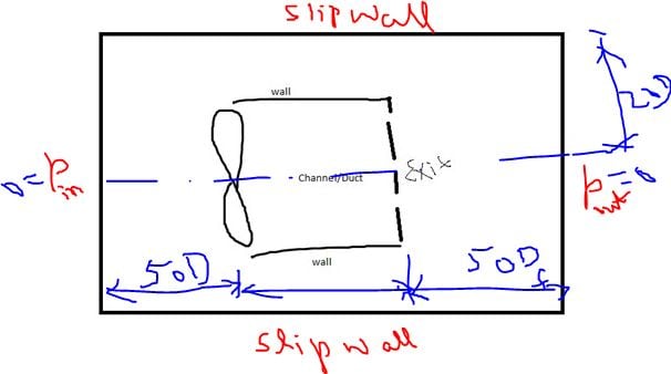
I know the power of the fan. I can plot the mass flow rate at the exit of the fan channel, but I couldn't figure out how to calculate the change in total pressure in the channel and at which point I should check the change.
If you solved your problem, could you explain how to, please?
Thanks in advanced.
-
- The topic ‘Simulating an axial cooling fan’ is closed to new replies.
-
2968
-
970
-
857
-
599
-
591
© 2025 Copyright ANSYS, Inc. All rights reserved.