
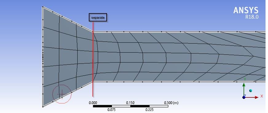
Edge sizing control is applying number of divisions and biasing unexpectedly


Viewing 6 reply threads
- The topic ‘Edge sizing control is applying number of divisions and biasing unexpectedly’ is closed to new replies.


