-
-
April 27, 2018 at 2:35 am
krishnadondapati
SubscriberHi,
I am using workbench 18.1 to simulate 4 point loading test on rock with Mohr - Coulomb criterion, but even after reaching its tensile limit its not showing any material failure.
so can some one help me to solve it
Thanks
-
April 27, 2018 at 3:10 am
-
April 27, 2018 at 6:27 am
krishnadondapati
SubscriberHi
Here I'm attaching project file
Â
-
April 28, 2018 at 6:56 am
krishnadondapati
SubscriberSorry I tried to attach the file but its size is 250MB may that's the reason it wasn't uploaded
-
April 28, 2018 at 3:47 pm
deepmech.maurya
SubscriberHello krishna
          According to me loading roller must have frictional contact with stone.
I know that brittle material fails with principal stresses. So use the principal stresses.
In ansys if you want to see the failure you have to use the material non linearity, otherwise it interpolates the linear elastic curve.
For accurate answer wait for Peter sir reply.
Below file is attached with friction having zero plastic strain.
thanksÂ
Deepak
Â
-
April 29, 2018 at 12:40 pm
peteroznewman
SubscriberHello Krishna,
There are many students here who have used the Mohr-Coulomb material model. If you edit the Title of this discussion and use "Mohr-Coulomb material model" instead of "Dondapati", some of them may even read this thread!
Did you read the ANSYS documentation for Mohr-Coulomb material model? It's under Mechanical APDL > Material Reference > Geomechanics. There you will find this
The model defines yielding when the combination of pressure and shear stress reaches the cohesion of the material particles. Yielding occurs when the shear stress on any plane in the material reaches this criterion:Â
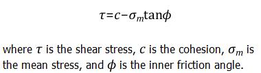
The value of c in your material is 19 MPa.Â
Did you read about the Mohr-Coulomb Stress Safety Tool in the documentation? It's under Mechanical Applications > Mechanical User's Guide > Using Results > Structural Results > Stress Tools.
Read the full page, not just this excerpt.
I recommend a few changes to your model.
Use Symmetry.
You have two planes of symmetry, half way along the length, and half way through the front-to-back depth. If you split the model on those two planes, you cut the volume to 1/4 and can therefore use smaller elements to get a more refined mesh that is still within the Student license limits. Another advantage is those planes take up 5 degrees of freedom on the body, so a displacement on the y coordinate is all that is needed to have a static model.
Replace Contact with Split Faces
Use a thin face to apply a displacement of Y=0 on the bottom and another thin face to apply a Y = -0.1 displacement on the top. It takes less time to solve if you have displacements than if you have contact.
Here is the result of the Stress Tool:
This shows the material has exceeded the failure threshold above about 40% of the applied displacement. However, this shows the failure is at the narrow face. Perhaps a wider face and smaller elements next to the face would be better for showing when the material on the center plane gets to the failure point.
Â
-
April 30, 2018 at 12:12 am
krishnadondapati
SubscriberHi Maurya,
I'm not able to open your file as yours is a future version. Can I know which version it was saved in?
Thanks
-
April 30, 2018 at 1:32 am
peteroznewman
SubscriberHi Krishna,
Much trial and error has gone into the attached model which I am going to let run overnight. I see that it can be difficult to create a model that converges up to the point of failure. Take a look at the attached ANSYS 18.1 archive and I will report in the morning if it made it further than the models with larger element sizes that ran faster.
Regards,
Peter
-
April 30, 2018 at 3:34 am
krishnadondapati
SubscriberThank you Peter
I'm going through your suggestion regarding M-C stress tool.
Â
Regards
Krishna
-
April 30, 2018 at 12:16 pm
deepmech.maurya
SubscriberHello krishna
 it is ansys 19 file.
But you must see the Peter sir ATTACHED FILE.Â
 he didn't use the friction at top contact as well as bottom.
But he is genius he removed the support by displacement (with 2 direction free)Â and loading tool by surface displacement with free movement in other directions.
So there is no meaning to check my file
All contact removed problem became linear.
regardsÂ
Deepak
-
May 1, 2018 at 7:30 pm
peteroznewman
SubscriberHello Krishna,
The file I provided above ran slow on a computer with only 16 GB of RAM. The solver needed more than that to run in memory, therefore it ran for a much longer time using the slow HDD as storage. It did eventually stop solving but managed to converge past the point where failure is predicted.
Here is the Safety Factor Plot with a Probe showing SF < 1 near the center of the beam on the bottom face. This is a view of the bottom of the beam.
Failure at the support was predicted at much less displacement, but that failure could be delayed by spreading out the contact force over a larger area. The failure at the center of the span cannot be mitigated, so is mostly independent of the testing setup.
The model ran for 103 iterations before stopping due to a failure to converge.
Your model had an applied displacement of -0.1 mm on the center pair of faces. Where did that number come from?
My model was able to solve until -0.0454 mm then could not converge, but the model predicts failure at the center at this displacement if you ignore the failure at the support face. The force reaction for this displacement was 977 N for the quarter model or 3908 N for the full model. Do you have experimental data to compare this with?
Regards,
Peter
Â
-
May 2, 2018 at 8:05 am
deepmech.maurya
SubscriberHello peter sir
            is this linear or non-linear problem after removing contact.
Material and geometric non linearity is not there, i confirmed. is SOF of Mohr-coulumb criteria?
thank youÂ
-
May 2, 2018 at 9:50 am
peteroznewman
SubscriberHello Deepak,
This could have been a linear analysis, since I am looking for the point where the material reaches its yield point and it is elastic up to that point. I set Large Deflection to On but that was probably unnecessary.
I have learned that a combination of using SOLID65 elements and the CONC material model will allow cracking to be computed on an element basis.
Regards,
Peter
-
May 4, 2018 at 2:40 pm
deepmech.maurya
SubscriberHello sir
        in my fracture mechanic tutorial i created the cracks in apdl. Upto ansys 18 version only formation of crack is there without propagation,in ansys 19 they provide the benefits of propagation.
KSCON i know, concentrated keypoint about which all analyses occur.
Variation of stress concentration without moving the crack.
Â
-
May 29, 2018 at 3:25 am
krishnadondapati
SubscriberHi Peter
Thank you for your info, Sorry for the late reply as I'm working on another one.
In the experiments, failure is initiated in the middle of the beam and also want to compare the results with the experimental strain values.
can you please give me an insight on identifying the displacement at the last converging point. Also, one more thing about the selection of no of steps and step time.
Â
Thanks & Regards
Krishna
Â
-
June 10, 2018 at 12:10 am
peteroznewman
SubscriberHi Krishna,
Sorry for the late reply also.
This post has some relevant insights on Step Control.
When the solver fails to converge and stops, the Deformation plots often show the Unconverged solution, which is not what I want to see, I want to see the last converged solution. To see that, go to the Tabular data table for that result and scroll the the end. In a 2 step solution, you will see the time is 2 on the last row but 1.235 on the second last row for example. Right click on that second last row and select Retrieve this result. Now you are looking at the last converged result. You can probe the displacement anywhere on that model.
You can do the same for strain, picking the second last row. Since your strain gauge was aligned along the length of the beam, request Normal Strain and pick the appropriate axis for the strain component. You can then probe to pick off the value at the location where the strain gauge was mounted to compare with the experimental result. You can select a node nearest the strain gauge and plot the time history of strain.
Kind regards,
Peter
-
- The topic ‘Mohr-Coulomb material model’ is closed to new replies.
- The legend values are not changing.
- LPBF Simulation of dissimilar materials in ANSYS mechanical (Thermal Transient)
- Convergence error in modal analysis
- APDL, memory, solid
- How to model a bimodular material in Mechanical
- Meaning of the error
- Simulate a fan on the end of shaft
- Real Life Example of a non-symmetric eigenvalue problem
- Nonlinear load cases combinations
- How can the results of Pressures and Motions for all elements be obtained?
-
3977
-
1461
-
1272
-
1124
-
1021
© 2025 Copyright ANSYS, Inc. All rights reserved.