Hello:
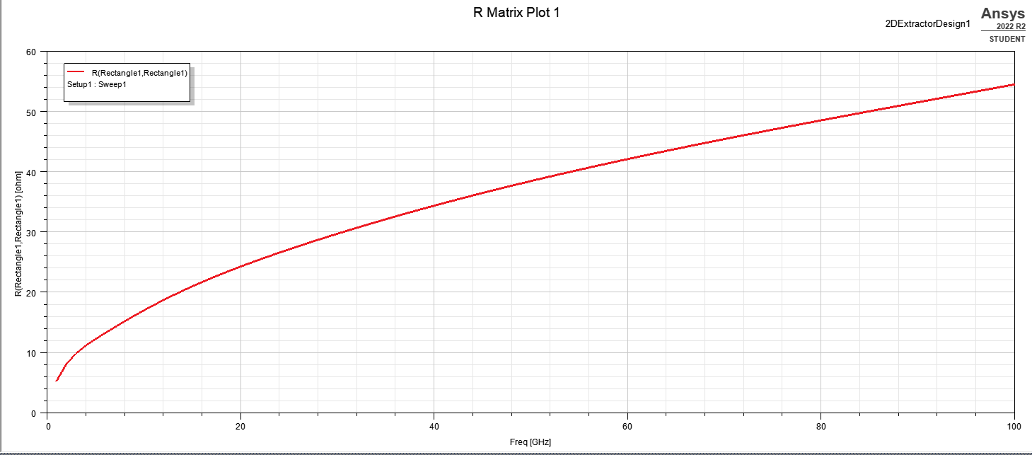
The figure shows the simulated resistance. This is considered to be the sum of the resistances of the two copper plates.
We want to know the resistance of one copper plate. As the two copper plates are the same size, we assume that half of the result obtained from the simulation is the resistance value from the simulation. The resistance R from the calculation is then calculated using the following formula.
R = 1/(σS)
S = 4δ( x - δ )
δ = 1/{(π*μ0*μr*σ*f)^(1/2)}
σ is the conductivity of copper at 20°C
S is the effective area
x is the length of one side of the copper sheet
δ is the skin depth
μ0 is the magnetic permeability in vacuum
μr is the non-permeability of the copper sheet
f is frequency
In the present figure, the simulated resistance at 100 GHz is about 27.2 Ω and the calculated resistance is about 20.6 Ω. We want to reduce the difference between these two values.
In case you are wondering, the above method worked well in Q3D Extractor. However, it is not working in 2D Extractor.


.png "simulation model")


