-
-
June 7, 2023 at 9:10 am
jayzhang
SubscriberHi,
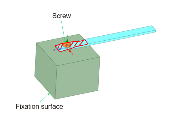
I create a simple model to illustrate my problem. In the below image, the bottom surface green box is the fixation surface. On the top surface of the box, a beam is fixed on the box by a screw. When I do modal analysis, the red shade area becomes really tricky to deal with. When the beam vibrates toward negative y direction, the box is supporting the beam and it is providing supports. However, when the beam vibrates toward positive y direction, only the screw functions as constraints. How could I deal with this problem in the modal analysis, harmonic analysis and random vibration analysis?
Thanks in advance.
Cordially,
JZ
-
June 7, 2023 at 9:25 am
Nanda
Ansys EmployeeHello JZ,
Does the screw have pretension defined? What are the contact defintions between those parts? Here's how I would model this:
- Frictional contact between box and beam, between screw head and beam.
- Bonded between screw and box.
- When doing prestressed analysis, there are 3 ways Ansys treats it's contacts, you can change this setting manually. By default it is set to "True status"
Apply Pre-Stress Effects for Implicit Analysis (ansys.com)
Regards,
Nanda.
Guidelines for Posting on Ansys Learning Forum
How to access ANSYS help links
-
June 8, 2023 at 1:45 am
jayzhang
SubscriberHi Nanda,
Thanks for your reply. I think the screw pretention should not have a big impact in modal analysis or vibration analysis. The contact between those parts matters more.The frictional contact between box and beam probably can not be representative in the case. Because the frictional contact will be converted to no separation or bonded contact. These two contact types are only linear ones. Correct me if I am wrong.
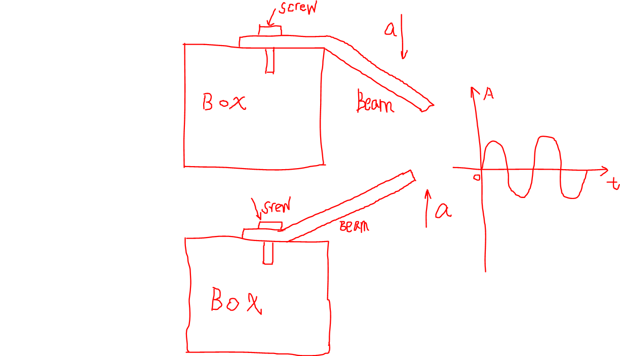
I draw a simple picture to further illustrate my problem below. Let’s only consider sinusoidal vibration. The top image indicates box and beam shared surface is supporting beam vibrating downwards. However, the bottom image indicates only screw and beam shared surface is constraining the beam vibrating upwards. We put the sensor at the end of beam in the test bench to extract the natural frequencies of beam. And we found a big deviation between simulation and test. However, we could not find a way to emulate the real scenario in the simulation.
Cordially,
JZ
-
June 8, 2023 at 8:18 am
ErKo
Ansys EmployeeHi
Correct these are linear type of contacts and can be used within harmonic response which is a linear type of analysis (see our courses for more info on this).
So to account for the nonlinear frictional contact you can look at nonlinear transient dynamic analysis.
All the best
-
- The topic ‘How to deal with non-linear vibration case in the ANSYS’ is closed to new replies.


- LPBF Simulation of dissimilar materials in ANSYS mechanical (Thermal Transient)
- Real Life Example of a non-symmetric eigenvalue problem
- How can the results of Pressures and Motions for all elements be obtained?
- BackGround Color
- Contact stiffness too big
- Element Birth and Death
- Python-Script to Export all Children of a Solution Tree
- Which equations and in what form are valid for defining excitations?

-
4592
-
1494
-
1386
-
1209
-
1021

© 2025 Copyright ANSYS, Inc. All rights reserved.


