-
-
December 13, 2017 at 12:39 pm
emirdegirmenli
SubscriberHello, I'm trying to get some vibration results from a modal test for thin plate glued braces such as guitar top plate. I'd like to model braces by using a solid element and thin plate (1,5mm) with shell element to adjust thickness easily and get better results. But when I draw a line on the surface to pull body in SpaceClaim, the surface is divided. and when I import model in Mechanical and adjust the thickness of plates, valleys are forming. I found  some information about solid and shell meshing but I am not sure If I make a mistake during drawing model in spaceclaim.Thanks,
Emir
Â
-
December 13, 2017 at 6:15 pm
peteroznewman
SubscriberHello Emir,
One way to fix this is to pull the three bridge solids, then create a New Component in SpaceClaim and create the surface body. You also want to select the SYS-1 at the top and Share Topology.
A best practice is to have a minimum of two elements through the thickness of thin parts meshed with solid elements. Below is the resulting mesh with Thick Shells unchecked.
When you check Thick Shells, it looks like this:
Note that the bridge solids are connecting with the midsurface of the shell elements. This introduces a very small error, which is negligible for thin shells, but if the shell element is relatively thick, there is another technique that allows the bridge solids to connect at the outer surface of the shell, offset from the midplane. I don't think you need that, but I will show that in the next post for completeness.
Regards,
Peter
-
December 13, 2017 at 6:35 pm
peteroznewman
SubscriberOne small source of error introduced by lengthening the bridges to reach the midplane of the shell elements is the mass that is being added to the model that is not there in the physical model. This could have a slight effect on the modal frequencies.
One way to eliminate this additional mass is to construct the bridge geometry to the correct height, and leave a gap to the midplane of the shell elements of exactly half the shell thickness.
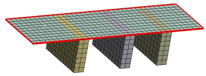
When viewed with thick shells, there is no "overlap" of the solid and the shell.
It is worth splitting the surface body at the tops of each bridge, then adding contact between these faces.
If the contact formulation is set to MPC, the contact elements can be seen after the solving the model.
This model has the correct mass of the physical system.
The table on the left has the results from this model with contact, the table on the right has the model in the previous post. Note the reduction in natural frequency caused by the added mass.
Save the attachment, change the extension from .txt to .wbpz and use ANSYS 18.2 to Restore Archive and you can see the examples in this and the previous post.
Regards,
Peter
-
December 14, 2017 at 5:02 pm
emirdegirmenli
SubscriberThank you, PeterÂ
Leaving a gap between solid and surface and using components during drawing a model are really working. I think now I can search contact types. I Â used bonded contact with two different formulations and IÂ got very different results. I think I can find the best appropriate method by comparing real experimental results. Bets, Emir
Â
-
October 13, 2022 at 6:43 pm
Zakary Adam
SubscriberGreetings,
For a complete (and practical) example for Connecting a Surface Body Edge to a Rigid Body Face in Ansys Mechanical, please visit: https://simutechgroup.com/connecting-a-surface-body-edge-to-a-rigid-body-face-in-mechanical/.
Â
-
- The topic ‘solid and surface connection’ is closed to new replies.
- Project lines/edges into a face with the direction normal to the face
- Script for subtracting models
- No preview in explorer with scdox file
- Multiple Instances of SpaceClaim taking multiple licenses
- Issues after installing new service pack 2024R1 (sp5)
- Spaceclaim file reference error
- Add-in Error Excel
- Problems with loading my Discovery Mesh into Fluent
- Missing SubDivWrapper.dll
- Fileformats
-
4102
-
1487
-
1318
-
1156
-
1021
© 2025 Copyright ANSYS, Inc. All rights reserved.