-
-
May 19, 2023 at 1:49 pm
Shiva2810
SubscriberHello everyone
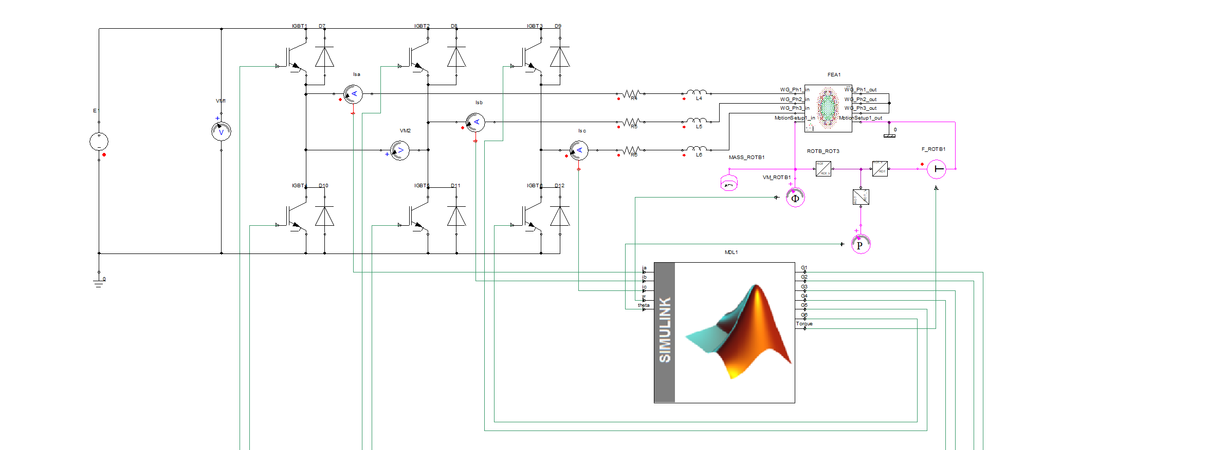
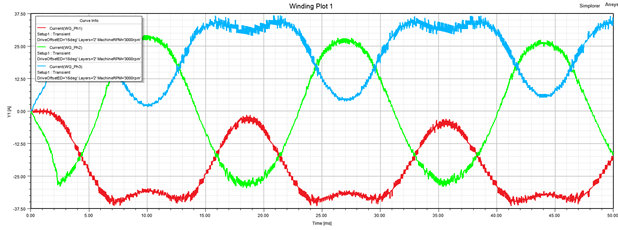
I am trying to perform co-simulation between Simplore and Simulink. Simplorer for PM Motor+Invertrer and Simulink for the control part. When I use the fractional model of the motor everything is fine and the results are as I expected. However, by connecting the whole motor model, I face a problem with the results. I attached a picture of the whole system and output current.
Could you please write a comment if you solved this issue earlier?
Thanks
-
May 30, 2023 at 11:22 am
phuonganhlovely.me
Subscriberi got same problem here
have u solve the problem? can u share with us ?
please contact with me by this email : Deleted (Rob). Please keep the conversations on here so others can learn from the outcome.
-
May 30, 2023 at 2:06 pm
Shiva2810
SubscriberHello.
I found that the Maxwell model is the problem here. Because I made the full model using MotorCAD, if you can make it using RMXprt then you will not face this issue.
-
May 31, 2023 at 2:39 am
-
-
-
May 31, 2023 at 4:57 pm
phuonganhlovely.me
Subscriber -
June 5, 2023 at 6:26 am
phuonganhlovely.me
Subscriber-
June 5, 2023 at 3:07 pm
Shiva2810
SubscriberHello
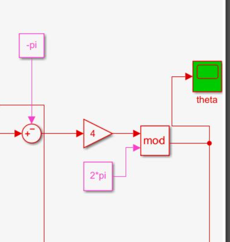
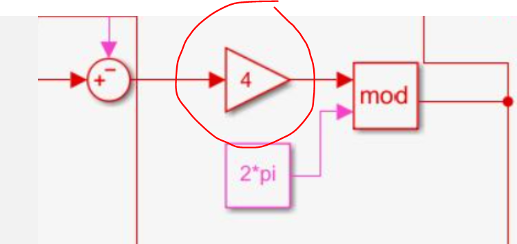
This part transforms the rotor angle (output of motor) to real rotor positions using those math blocks.
To understand better, perform the exact model in Simulink.
-
June 6, 2023 at 1:45 pm
-
-
-
June 6, 2023 at 1:47 pm
Shiva2810
Subscriberthe number of pole pair. here the motor has 8 poles.
-
June 6, 2023 at 3:52 pm
phuonganhlovely.me
Subscriberthanks you for your kind of reply.
i have another problem is facing with warning 10907. did u meet this warning during simulation ?
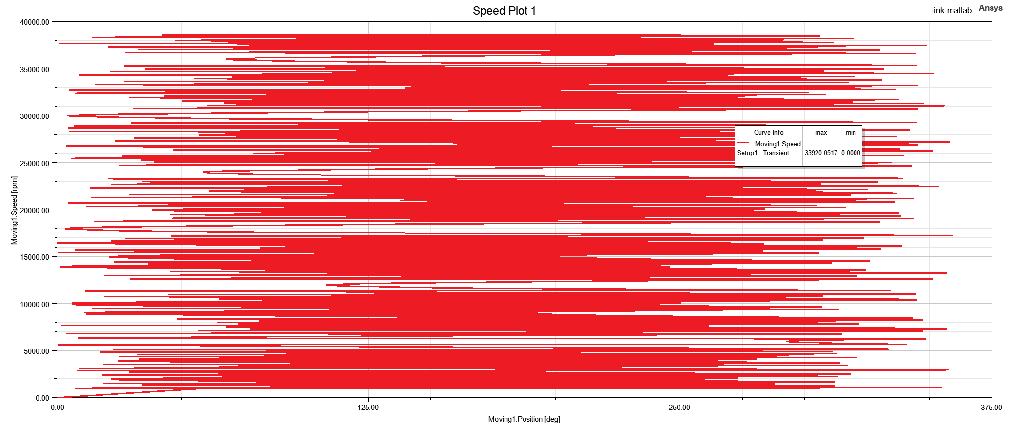
the connection in the the model it is show in the figure below and when i click on the warning the connection will be show. i dont know how to solve it for long time. the simulation is completed with no error but the feedback result of omega and theta is not correct. can you give me some solution to solve it.
best regards
-
June 7, 2023 at 8:46 am
phuonganhlovely.me
Subscriberplease send the example. The problem is not solved. thanks you
phuonganhlovely.me@gmail.com
-
-
June 8, 2023 at 4:19 pm
HDLI
Ansys EmployeeFor iteration warning, please increase iteration number in TR option setting or add "SIMPARAM" to monitor it. If the iteration just reaches max. number for a few steps, the simulation is OK.
Please review this /forum/forums/topic/motion-setup-terminals-in-ansys-maxwell-simplorer-cosimulation/
HDLI
-
June 11, 2023 at 9:28 am
phuonganhlovely.me
Subscriberi think the warning cause the error result when simulation.
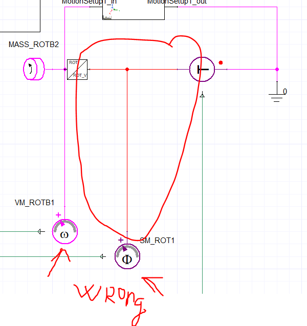
i would like to know how to choose the component measurement mechanical in simplorer they have 2 type of mechanical: displacement force representation and velocity force representation ( ex: SM_ROT or SM_ROTB…)
also for physical domains component.
-
-
June 26, 2023 at 6:47 am
-
June 26, 2023 at 8:12 pm
HDLI
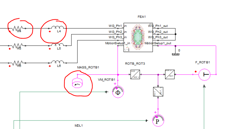
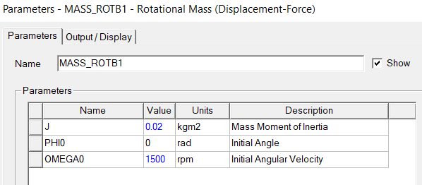
Ansys EmployeeWhen simulating 2D model with stranded winding, resistance is phase resistance and inductance is end winding inductance. In Mass_ROTB1, you may need to enter mass moment of inertia.
HDLI
-
July 1, 2023 at 7:44 am
-
-
- The topic ‘Simplore+Simulink co simulation problem’ is closed to new replies.


-
4618
-
1530
-
1386
-
1210
-
1021

© 2025 Copyright ANSYS, Inc. All rights reserved.

