-
-
May 15, 2023 at 11:31 am
Aditya Wani
SubscriberI want to generate an elliptical part with a 1.5-mm extrusion, but I don't know how to make it asymmetrical. Can somebody assist with this in more basic dimensions?
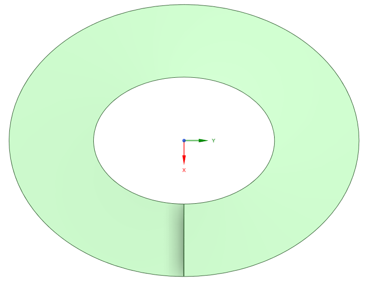
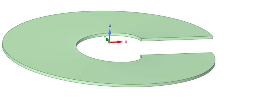
I initially made two ellipses and extruded them to a thickness of 1.5 mm. Next, I made a rectangle with a height of 1 mm and stated, "Cut material," which caused the component to be cut with a 1 mm gap. However, I now want one end of the part to be 1.5 mm higher than the other. How to perform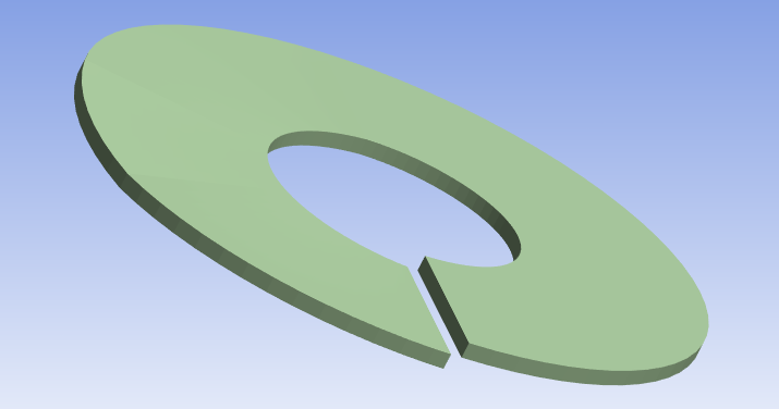
-
May 16, 2023 at 7:39 am
Nanda
Ansys EmployeeHello Aditya,
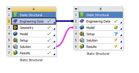
There might be someway of modelling it in CAD interface itself, but I'm not aware of it. I do have a way of doing this in Workbench. Use this model in Static structural analysis system. For one of the end face use fixed support, and for the other face, use a displacement load of 1.5mm in one of the axis and 0mm displacement to other two axis. You will get your deformation plot from total deformation.
You can export this deformed geometry into a new analysis system and use it as a new geometry. You need to map solution cell of old system to model cell of new system.
This is one way of doing it, I'm pretty sure there might be some easy CAD modelling featuring itself to generate what you want. Hope this helps.
Regards,
Nanda.
Guidelines for Posting on Ansys Learning Forum
How to access ANSYS help links
-
May 16, 2023 at 8:57 am
Aditya Wani
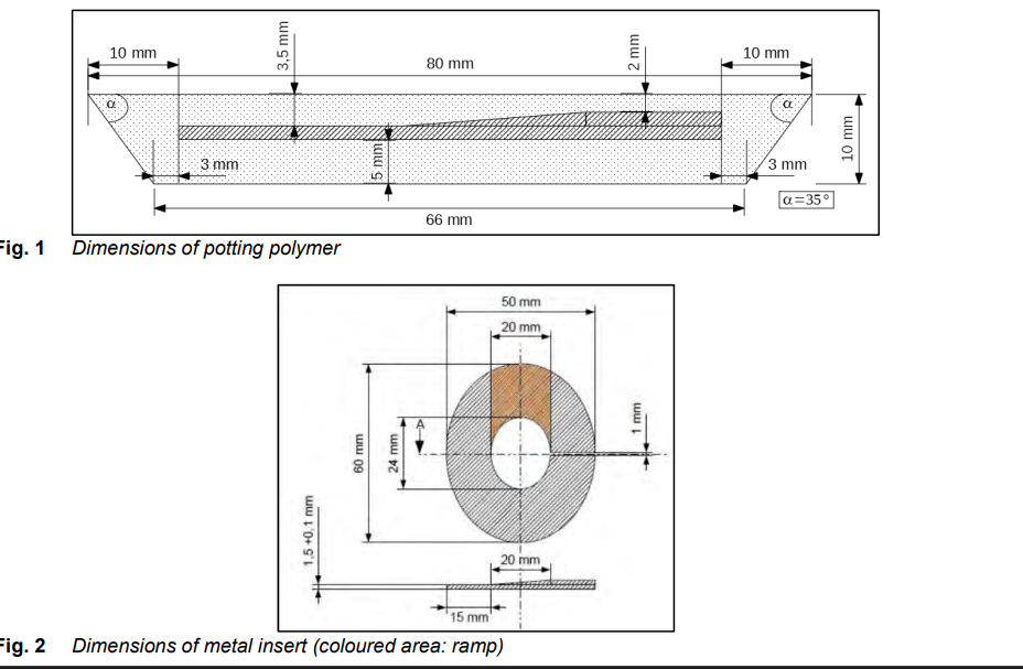
SubscriberI would like to clarify that my requirement is not limited to creating just the individual component. Instead, I intend to incorporate this geometry within a conical-shaped polymer. By designing the geometry in this manner, I will have the flexibility to parameterize the distance between the polymer and the specimen, which would provide better control and adjustability for my project. Do you any idea about creating this geomtry in design modeler or spacelaim?
-
May 16, 2023 at 9:04 am
Nanda
Ansys EmployeeHello Aditya,
Could you provide further information like a rough sketch or photocopy of what you're trying to model. This will make us understand your issue with large number of audience, so that you'll get a solution as soon as possible.
Thanks.
-
May 16, 2023 at 9:11 am
-
May 16, 2023 at 11:16 am
peteroznewman
SubscriberHello Aditya,
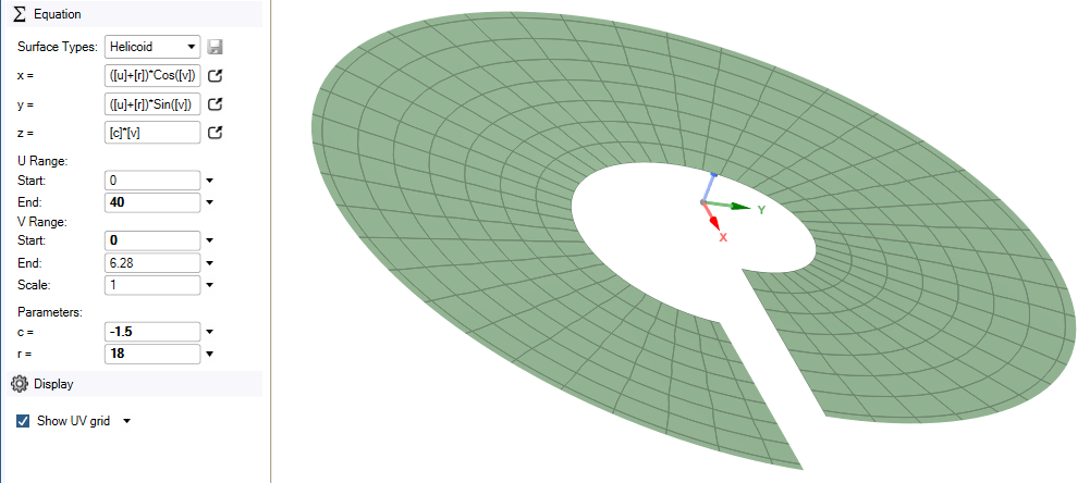
In SpaceClaim, on the Design tab is the Equation button. Here you can make a Helicoid shaped surface.
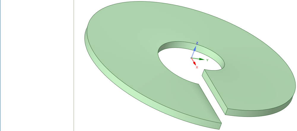
Then use the Pull tool to add thickness to the surface.
The shape of this part is circular. If you are good at math, you can modify the equation and type in the formula for an ellipse, but I will make a sketch, draw an inner and outer ellipse and extrude those to cut this solid.
This shows how to make the shape you first asked about which has edges that are spirals. The last image you show has a ramp feature and can be constructed without starting with a helicoid.
-
May 16, 2023 at 12:24 pm
Nanda
Ansys EmployeeHello Aditya,
I just tried what peter suggested, it worked for me. Try it from your end and mark peter's comment as "Solution answered", it will help other user's who are looking to build similar geometry.
Thanks
-
June 23, 2023 at 6:18 pm
Aditya Wani
Subscriber -
June 23, 2023 at 11:52 pm
peteroznewman
SubscriberChange the value of c to make the two ends go edge-to-edge.
-
June 30, 2023 at 9:24 am
Aditya Wani
Subscriberwhich value should i put of "C" to get geometry mentioned above. Can you give me exact value of "C"and other parameters?
-
June 30, 2023 at 11:33 pm
peteroznewman
SubscriberThe value of "C" is the thickness of the Pull you will do to make the surface into a solid.
-
July 1, 2023 at 7:14 am
Aditya Wani
Subscriberbut after putting value of C as -1.5 is showing some gap between upper and lower part as show in above figure.
-
July 1, 2023 at 11:00 am
peteroznewman
SubscriberLook at the equation, it says z = c * v
v goes between 0 and 6.28 so the step in the surface is 6.28*1.5 = 9.42
Let the thickness of the Pull be t.
t = 6.28*c
Solve for the value of c.
-
- The topic ‘Creating an asymmetric shape in Design Modeler’ is closed to new replies.


-
4798
-
1576
-
1386
-
1242
-
1021

© 2026 Copyright ANSYS, Inc. All rights reserved.


