-
-
May 12, 2023 at 1:35 pm
Adrien
SubscriberHello,Â
I performed a modal analysis and exported in a text file X,Y,Z,RX,RY,RZ displacement (in that case, mode shape) of some interesting nodes: here an example
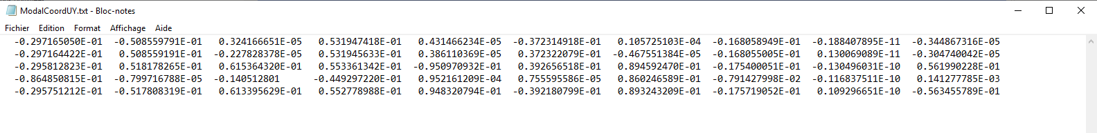
Line : node (6 nodes here)
column : mode (10 modes)
Then, I performed a harmonic analysis with the MSUP method (mode-superposition) linked with the previous modal analysis, and write the MCF file related to it (HROPT,MSUP, , ,YES).
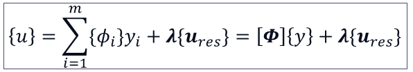
I know that the idea of the MSUP method is to calculate the displacement like this :
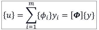
That is to say, express the displacement vector in the modal basis formed with the mode shapes calculated during the eigenproblem in the previous modal analysis.
Then, i want to take into account the residual vector, which is the highest modes contribution. When i enable including the residual mode (RESVEC, ON), or the harmonic analysis settings
, the MCF file contains one more mode (last column) that is the residual mode :
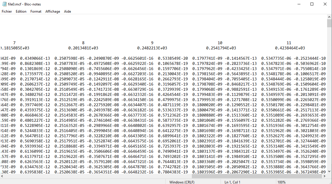
In my modal analysis, I only chose the 10 first modes, and the 11th one refers to the residual mode.
Now, I have all i need to calculate the frequency response.
I guess I just have to make "sum(phi_i * y_i) + residual vector" at each frequency excitation to calculate that, but it doesn't give me the good result. In fact, i'm comparing result to ANSYS and it doesnt correspond. Here is the comparison response at one particular node :
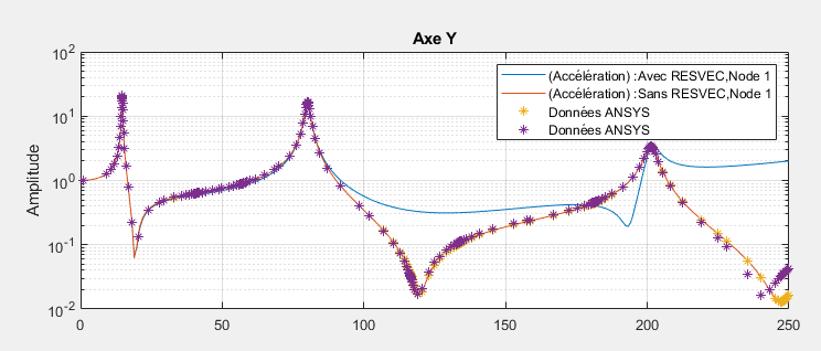
Blue : "by hand" calculation in MATLAB with MSUP method, with residual mode (RM)
Red : "by hand" calculation in MATLAB with MSUP method, without residual mode
Yellow : Ansys frequency response with MSUP method, without residual mode
Purple : Ansys frequency response with MSUP method, with residual mode
The yellow and red curves are corresponding, which is normal because i just made by hand the same calculation than ANSYS.
Yet, the red and purple curves does not correspond, and it should. Is the operation "sum(phi_i * y_i) + residual vector" wrong ?
To resume : I obtain the good results when i'm performing the MSUP method whithout RM, but not the good results in MSUP method with RM.
Thanks,
Adrien
-
May 16, 2023 at 6:49 am
Ashish Khemka
Forum ModeratorHi Adrien,
Please see if the following courses are of help to you:
Mode Superposition Method | Ansys Innovation Courses
Utilizing Residual Vector Method in Harmonic Analysis - Lesson 3 - ANSYS Innovation Courses
Regards,
Ashish Khemka
-
May 16, 2023 at 12:20 pm
Adrien
SubscriberHello,
Thanks for your response and your sharing. I already saw this course and, as i'm calculating displacement by hand (in matlab), this course doesn't correspond to what i'm looking for. Indeed, i want to know what follow:
I know that the residual vector option lets ansys write a last column in the mcf file which correspond to a pseudo-mode (the 11th in my original message). I also know that I have to add it to the displacement calculated by the mode superposition method :
So the result with residual vector gives me something like this:
Where {u_res} is the residual vector calculated by ansys in the mcf file (the last column).
And lambda is the corresponding coordinate (that's something i've found after writting this post). For exemple, in my example, i found empirically that lambda = -0.135 gives me the exact graph i want (the same as ansys), but i don't know how to find that coordinate (somewhere in the rst file ?). If you have any idea, let me know
Regards,
Adrien
-
May 16, 2023 at 12:42 pm
Adrien
SubscriberUpdate : in my harmonic analysis, the previous modal analysis is restarted with the command ANTYPE, MODAL, RESTART (as shown in the ds.dat file). During this restart, my resvec command is taken into account :Â
/solu
antype,modal,restart   ! restarting the modal analysis
modcontrol,on,on ! enforced motion turned on
resvec,on
mxpand,,,,yes,,yes   ! expand requested results and write them to file.modeit probably means that some pseudo mode shape is calculated during this restart, right ? and then stored in the mode file of the modal analysis ?
-
-
May 16, 2023 at 12:56 pm
Ashish Khemka
Forum ModeratorMechanical includes residual vectors by performing a modal restart. Thus, the residual vectors are not included in the original modal analysis system or in its results.
Regards,
Ashish Khemka
-
May 16, 2023 at 12:59 pm
Adrien
SubscriberYes, but how can I access to the numerical value of this residual mode shape ? Storing it in a variable for example…
Â
-
-
May 16, 2023 at 3:13 pm
Adrien
SubscriberUpdate : I think I have found something, for those who were interseting.
*DMAT, mode, D, IMPORT, RST, file.rst, 11, 11
*EXPORT, mode, MMF, modeThis APDL command launched in the harmonic analysis (prior to the ANSYS SOLVE command) allows us to find the mode shape of the residual vector, in addition to the coordinate value of the response at each frequency in the mcf file. It was stored in the RST file after restarting the modal analysis for the RESVEC command (or any other option that requires a modal analysis restart).
-
May 17, 2023 at 5:23 pm
dlooman
Ansys EmployeeIt's easier to do a hand calculation of mode sup results outside of Workbench. The APDL input file below extracts a real mode and a residual vector and outputs the modal tip displacements. Multiplying these modal tip displacements by the complex mode coefficients on the MCF file produces the harmonic solution output at the end of the input.
/prep7et,1,188,,,2mp,ex,1,3.0e7mp,nuxy,1,0.3mp,dens,1,0.000754sectype,1,beam,rectsecdata,2.0,1.0n,1n,2,40e,1,2d,1,alld,2,uz,0finiÂ/soluantype,modalmodop,lanb,1mxpand,1,,,,,yesresvec,on,f,2,fy,100solvefiniÂ/post1set,1,1phi_1=uy(2) ! tip displacement for mode 1set,1,2phi_2=uy(2)Â ! tip displacement for resvecÂ/soluantype,harmonichropt,msup,,,yesharf,300nsub,1dmprat,0.025resvec,on,f,2,fy,100solvefiniÂ/soluexpass,onexpsol,1,1solvefiniÂ/post26nsol,2,2,uyprvar,2Â Â Â Â Â Â Â ! harmonic solutionÂMCF File:Modal Coordinates File - Harmonic Solution
ANSYS 2023 R1 Â Â Â Â Â BUILD 23.1 Â Â Â Â UP20221128 Â Â WINDOWS x64Â
05/17/2023 Â Â Â 13:04:15
Title: Â Â Â Â Â Â Â Â Â Â Â Â Â Â Â Â Â Â Â Â Â Â Â Â Â Â Â Â Â Â Â Â Â Â Â Â Â Â Â Â Â
Number of Modes: Â Â 2
 Mode:            1               2
 Frequency:      0.4129213E+02         0.3332116E+03
  Frequency      Coordinates...
 0.3000000E+03 -0.2417264E-03 -0.1695691E-05 -0.8894822E-03  0.2114026E-03Â
-
- The topic ‘Calculate by hand frequency responses including residual vectors’ is closed to new replies.
-
4929
-
1638
-
1386
-
1242
-
1021
© 2026 Copyright ANSYS, Inc. All rights reserved.


