-
-
April 17, 2023 at 4:32 am
atfkerem76
SubscriberHello,Â
I was working on a material which has 3 layers. I wanted to optimize its individual layer thicknesses in order to maximize its reflectance. For that I used optimization tool in FDTD, and chosed parameters like this:Â
But after running this optimization layers got randomly positioned, collided with each other and their thicknesses also changed. I actually had some doubts but gave it a shot anyways. Here is one of the optimization results:
What I actually want to do is, optimizing the layer thicknesses while keeping their positions and other parameters reasonable (not colliding with each other or got randomly placed). How can I do that?Â
Here is the default model:Â
Thanks.Â
-
April 17, 2023 at 7:17 pm
Guilin Sun
Ansys Employee
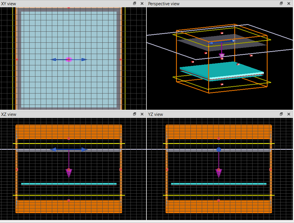
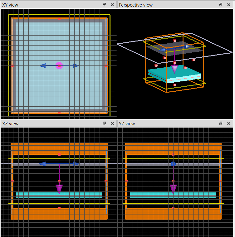
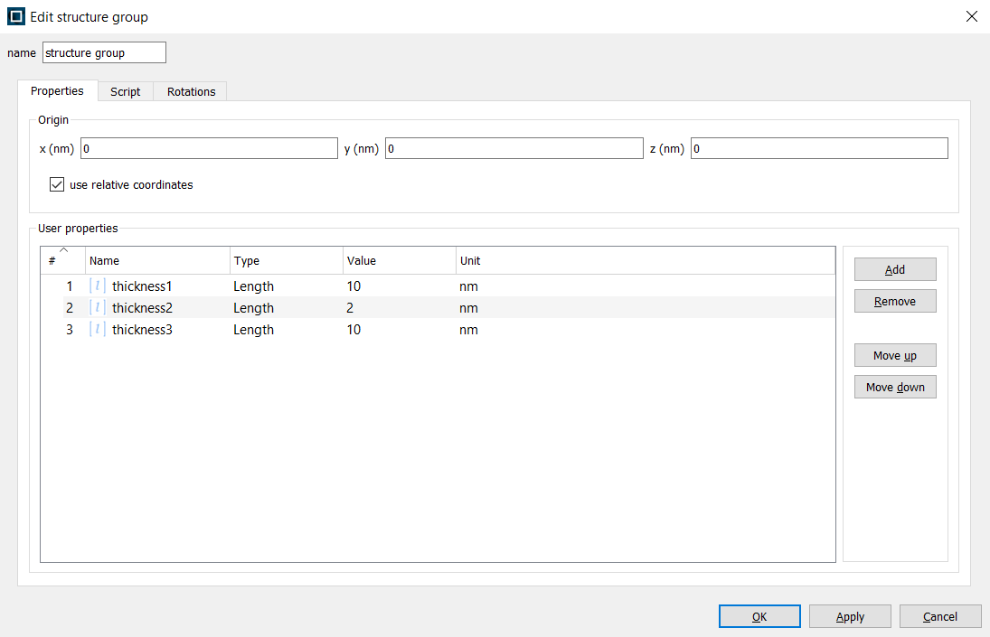
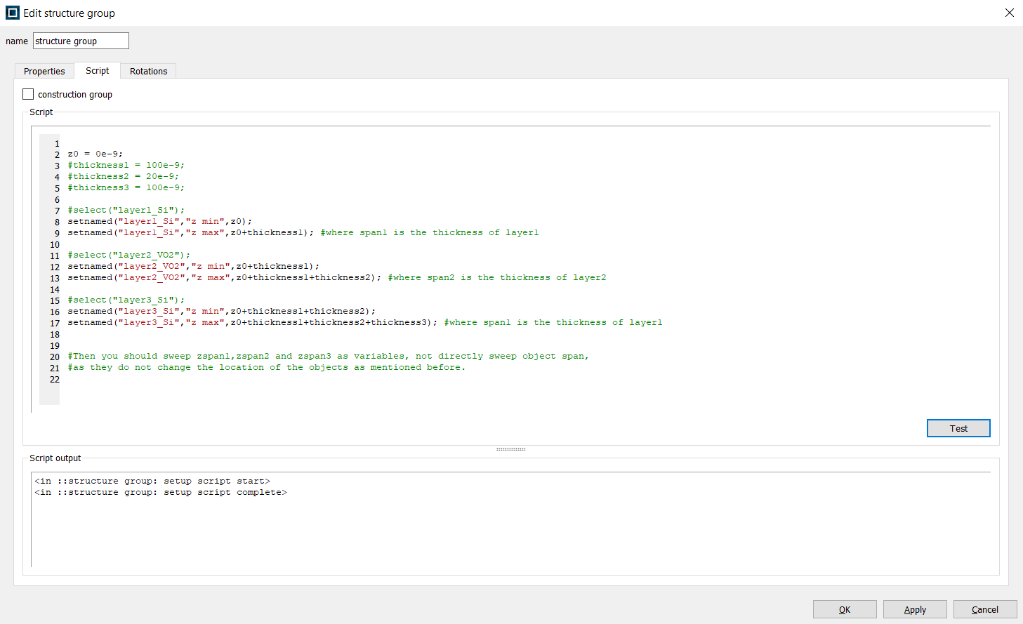
This is a common issue, as span is only a length. It does not change the position of the object. In order to get correct geometry, you will need to use script in "model" (or structure group if you wish) to set the location/span of the objects. For example, suppose your structure is layered from layer1, layer2 to layer3, bottom up, and layer 1 begins from z0, then you can set
setnamed("layer1","z min",z0);
setnamed("layer1","z max",z0+span1); #where span1 is the thickness of layer1
setnamed("layer2","z min",z0+span1);
setnamed("layer2","z max",z0+span1+span2); #where span2 is the thickness of layer2
similarly for layer 3.
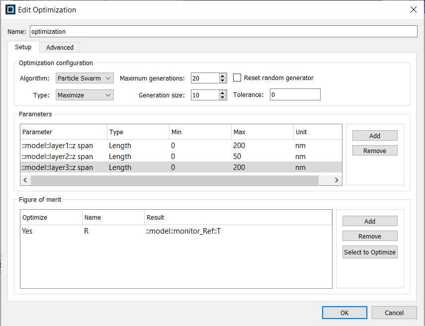
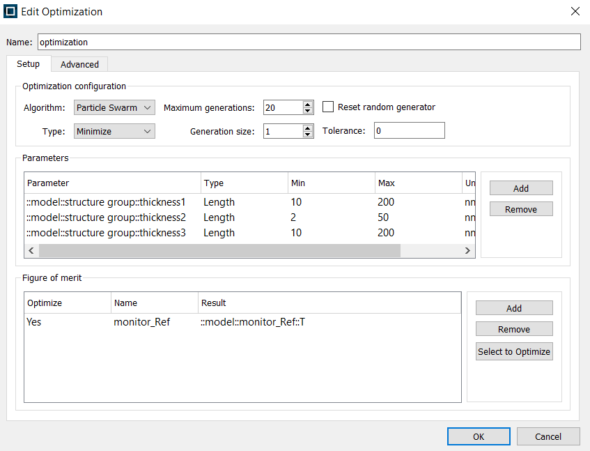
Then you should sweep span1,span2 and span3 as variables, not directly sweep object span, as they do not change the location of the objects as mentioned before.
Please refer this example: https://optics.ansys.com/hc/en-us/articles/360034922873-Parameter-sweep-utility
-
April 20, 2023 at 2:34 am
atfkerem76
SubscriberI tried your instructions in previous post. Basically I created a structure group, wrote a script for that and created some properties:
I created thickness1, thickness 2 and thickness3 for span1,span2 and span3, respectively. And then I wrote this script:
Then I went to the optimization tab and adjusted it like this:Â
I chosed parameters that I created before, and set a frequency domain field-profile monitor which is named "monitor_Ref". Objects tree looks like this:Â
So far it worked well. It creates a random structure and saves files to analyze. But after finishing the first generation of simulations, it gaves this error:
I tried to fit the monitor into the simulation region, changed the type of monitor to frequency domain field and power but none of them worked. Since this is the first time I try to use optimization tool so maybe I'm missing something, even though those are pretty straight forward. What could be the reason for this issue and how can I solve it?Â
-
April 20, 2023 at 3:37 pm
Guilin Sun
Ansys EmployeeWhat data you extract from "monitor_ref"? I guess it is the fields, not the transmission. Fields will change its data dimension when objects changes. Only fixed dimension such as transmission can be extracted.
In addition, optimization is for a scalar FOM. You cannot optimize more than one value of FOM using the built-in particle swarm method.
This is different from the original post. Please write a new post if you have further questions.
-
April 22, 2023 at 6:39 am
atfkerem76
SubscriberActually I wanted to extract transmission data, but I'm not sure the way I did is correct. I just tried to follow up the same instructions in this video:
ÂSo that means I cannot optimize thickness1, 2 and 3 simultaneously? If thats it, I can write a new post.
-
May 2, 2023 at 7:16 pm
Guilin Sun
Ansys EmployeeWhy not? you should be able to optimize all layer thickness. The example illustrates for a single layer. Once you set the structure properly, you should be able to optimize them.
In addition, you may also try to use stackrt which is analytical solutions. However it does not provide optimization. You can do sweep using script.
You can write a new post for any new questions.
-
- The topic ‘Design optimization issues for multilayer materials in FDTD’ is closed to new replies.
- Response constraint not allowing structural optimization to solve.
- Feasibility Check – FT Sensor Flexible Chassis Design Optimization
- Issue with Reaction Force Scaling in ¼ LS-DYNA Model Simulation
- Method to properly export/import APDL readable solids
- Extremely Low Rotor Core Loss in Rotor Lamination Simulation Using Maxwell 2D
- OptiSlang sensitivity analysis can’t assign different values to the parameters
- Data management and subsequent insertion of variables/responses
- Compute Adjoint sensitivity wrt viscosity
-
3597
-
1243
-
1092
-
1068
-
953
© 2025 Copyright ANSYS, Inc. All rights reserved.