TAGGED: Discovery Live
-
-
November 27, 2019 at 12:02 pm
garias
SubscriberHi all,
One of our customer is experiencing a very strange behavior of Discovery Live. The model is similar to a long slender pipe subjected to internal and external pressure, it is fixed at one end and guided axially at the other end and halfway of the length of the pipe. I have attached the model. The results changed drastically depending where the fidelity bar is. Low fidelity and high fidelity seems to give reasonable results, deformation shape and magnitudes seems to be OK, however at some intermediate fidelity locations the results are totally wrong. see pictures attached.
I am running this mode in Discovery Live 2019 R3 on a Dell (Alienware) laptop with and Nvidia GeForce GTX 1060, see details below.
Operating System: Windows 10 Pro, 64-bit
DirectX version: 12.0
GPU processor: GeForce GTX 1060
Driver version: 431.86
Driver Type: Standard
Direct3D API version: 12
Direct3D feature level: 12_1
CUDA Cores: 1280
Core clock: 1404 MHz
Memory data rate: 8.01 Gbps
Memory interface: 192-bit
Memory bandwidth: 192.19 GB/s
Total available graphics memory: 14272 MB
Dedicated video memory: 6144 MB GDDR5
System video memory: 0 MB
Shared system memory: 8128 MB
Video BIOS version: 86.06.3E.00.10
IRQ: Not used
Bus: PCI Express x8 Gen3
Device Id: 10DE 1C20 07701028
Part Number: 2914 0030
Also when reviewing displacements in the Y and Z direction, the results seems to be wrong in the cases where the overall solution seems to be correct. It looks like the values are 1 order of magnitude bigger that it should be and also Y and Z are interchanged.
Any Idea why this behavior? in this particular case is quite simple to detect that the solution is totally wrong but what about in a more complicated assembly? identifying this behavior could be very difficult.
Any idea to avoid this problem is very welcome.
Thanks a lot for your help
🛈 This post originally contained file attachments which have been removed in compliance with the updated Ansys Learning Forum Terms & Conditions -
November 27, 2019 at 8:58 pm
Brian Bueno
Ansys EmployeeGabriel Arias
The wall thickness of the pipe is 8 mm, and the overall length is 7100 mm. The fidelity within Discovery Live depends heavily on the size of the model. In this case, the difference between these two values is huge, so it's not surprising that the results are behaving strangely.
For more information about simulation fidelity in Discovery Live, please refer to the following articles:
Discovery Verification and Benchmark Cases
Discovery Live: “Thin” geometric features and relative GPU adjustments
-
November 28, 2019 at 9:34 am
garias
SubscriberHi Brian,
Thanks a lot for your answer and links. I was aware of the limitaion of the solver and also aware that the bigger the model size the bigger the element size so some details of the geometry might be ignored. But it is not the case in this model. Yes, the model is big, and Yes, the thickness is small, so the ratio is huge, however with an elemetn size of 6.7 (fidelity bar closer to the speed end) the behaviour is captured same as if the the element size is 3.75 (fidelity bar closer to the Fidelity end) and looking at the results it looks like the model is been meshed (no gaps in the mesh or holes through the model) but if the element size is in-between ~5mm the solution is totally different and wrong, This is what I'm strugling to understand, if details are captured at a bigger element size, why it is not able to do it if the element size is smaller?
According to the verification manual some of the expamples shows errors of a bout 10 or 20% which I understand, but in this particular case the error in displacement is massive (~3000%) and it is not that the model is not been entirely meshed, at least if you create a section that slides the model along the axis so you see half symmetric model you can see that the thickness is been fully meshed (element size used is smaller than the pipe thickness).
Do you have any more comments on this? It might be that my interpresations of the element size used for meshing is wrong, but I understand that if the element is 6mm, the type of mesh used is a regular cartisian mesh with all the elements size 6x6x6mm. Am I wrong?
Thanks again for help and comments
Gabriel Arias
-
December 2, 2019 at 10:49 am
garias
SubscriberHi Brian Bueno ,
Any new comments on my last replay. Also I've changed the model to make more simple and also to reduce the big Thk/Length ratio. still the results does not look good. the model Attached is a 1/4 of a straight pipe 100mm long thich a 5mm thickness wall. Looking at the radial displacement resutls you could see that the model is not behaving correctly. Would you be able to comment on this? what is the max ratio length/thk that Discovery Live can handle?
Again thanks a lot for you help.
🛈 This post originally contained file attachments which have been removed in compliance with the updated Ansys Learning Forum Terms & Conditions -
December 4, 2019 at 11:42 am
garias
SubscriberHi Brian,
Sorry to bother you with this again, but do you have more information about these issues?
-
December 5, 2019 at 5:06 pm
Brian Bueno
Ansys EmployeeGabriel Arias
Sorry for the delay in responding. I will have to consult with the development team about this to see what their conclusion is.
What results are you expecting for the Small Straight Pipe model? The maximum deformation in Y on my PC is .00347 mm
I did notice that your calculators are set to measure the deformation along a curve at each end. However, for this calculator to display results, the statistical operator setting needs to be None. The values will then be displayed along the length of the curve.
-
-
December 6, 2019 at 10:10 am
garias
SubscriberHi Brian Bueno
Thanks for getting back to me on this issue. The correct results for this case should be an uniform radial displacement on the outer face of 0.0028mm and in the inner faces of 0.0021mm. The two calculators I've used were to give me the radial displacement, due to the symmetry this can be done measuring max disp in X and or Y. But you could see that the displacement in X or Y is not uniform it should looks like stripe of uniform colour along the pipe axis as shown in the pictures attached.
Also in a different example, a simple straight pipe with internal pressure and fixed at one end, there solution produces, with Max fidelity, the pipe to bend which is obviously wrong, and the longer the pipe the more obvious the error is. I've also attached a model that shows this behavior and a picture.
Hope this helps to debug the problem.
Thanks a lot for all your efforts.
Gabriel Arias
🛈 This post originally contained file attachments which have been removed in compliance with the updated Ansys Learning Forum Terms & Conditions-
December 6, 2019 at 2:54 pm
Brian Bueno
Ansys EmployeeGabriel Arias
The overall displacement magnitude rendering is correct because the red area is where the pipe is getting longer.
The pictures shown with the radial color bands are using a “cylindrical” coordinate system. Discovery Live does not support rendering with this method.
For the longer pipes it is a matter of having enough GPU memory to capture the geometry.
-
-
December 6, 2019 at 4:29 pm
garias
SubscriberHi Brian Bueno
There are a few issues open which I feel are not answered yet.
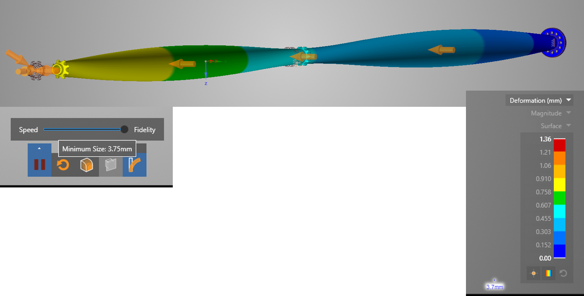
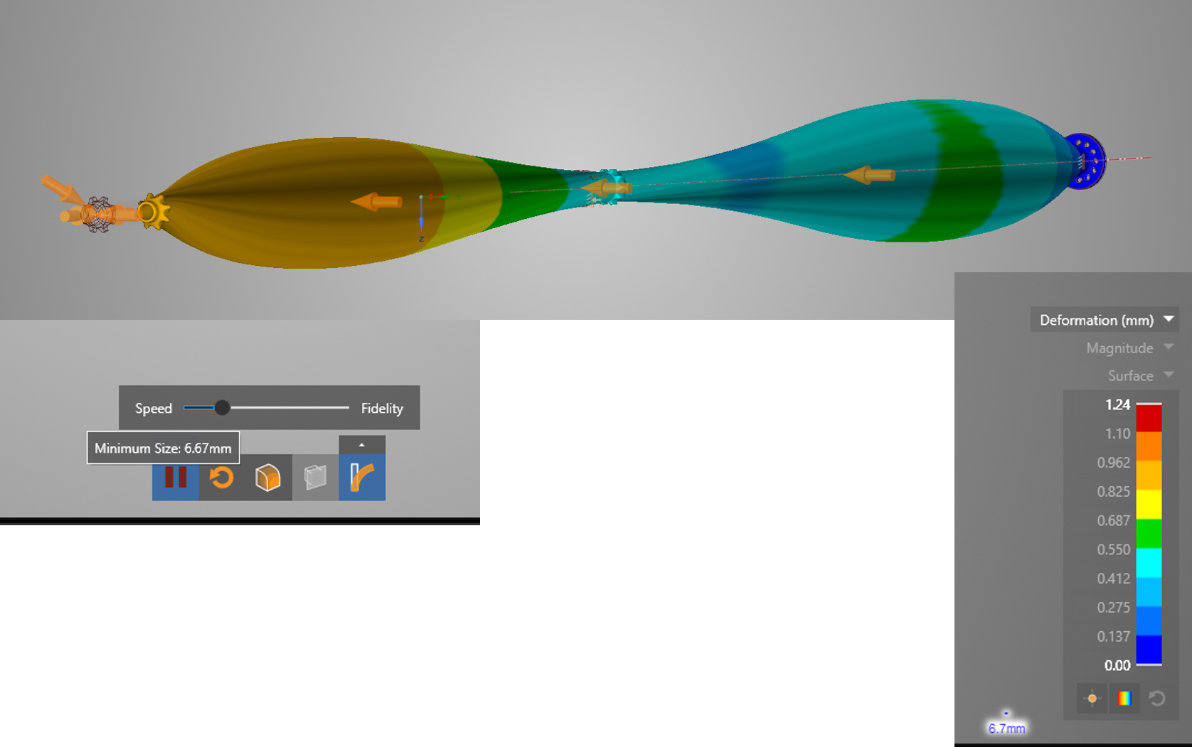
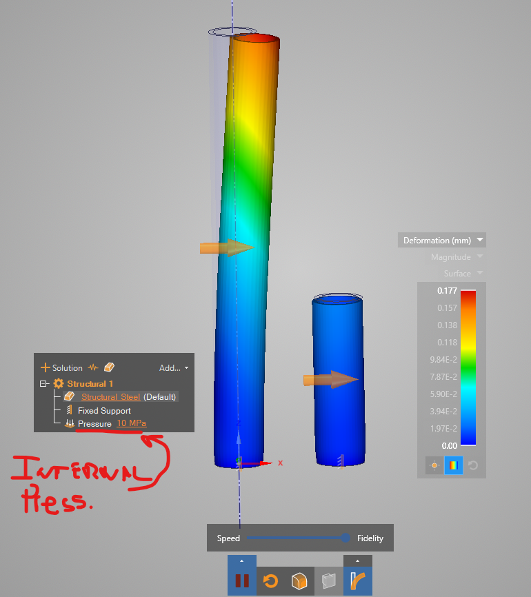
1 - Original long hollow pipe drilling bit model.
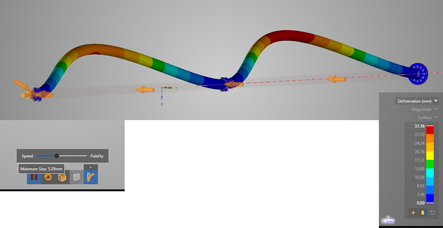
The total deformation at some fidelity points is totally incorrect however it is roughly correct at low and high fidelity. This behaviour, from a user point of view, does not make sense and it is quite puzzling.
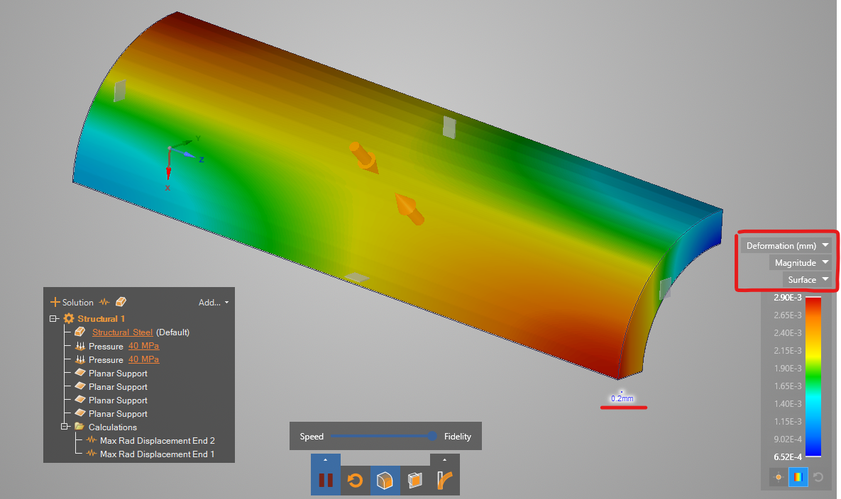
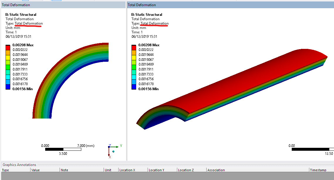
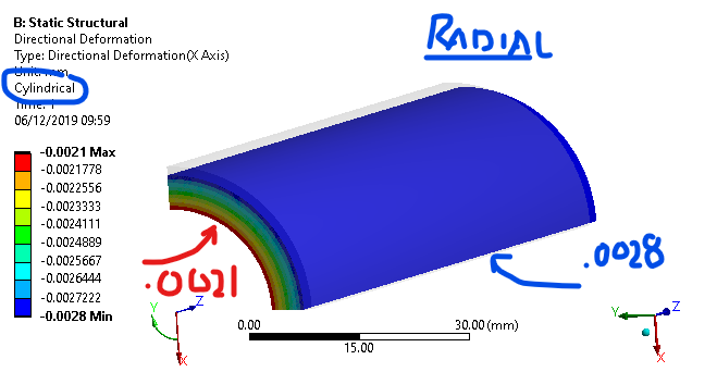
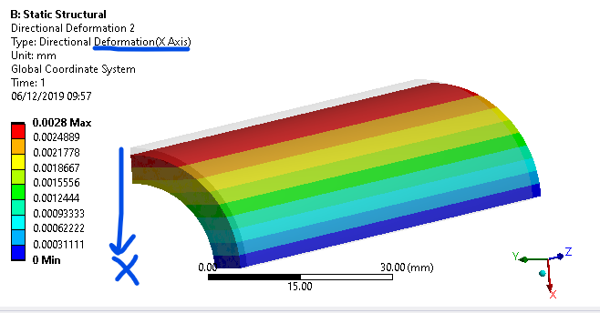
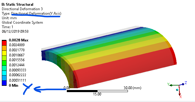
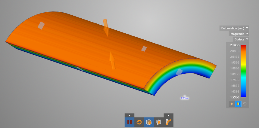
2 - In order to avoid the problem of a large thickness/length ratio I've created the second model. This is a quater of a short pipe. It has symmetry boundary conditions, and equal internal and external pressure and it is axial fixed at one end. You are right, the overall displacement is correct, however beacause it is one order of magnitude bigger than the radial expansion it is hidding the problem of the radial displacement. If you run the same problems but fixing axially both ends the problem is highlighted. The element size this model is using in my machine is 0.2mm which is 25 time smaller than the actual thickness, small enough to capture any details. (I have attached picture and database).
In order to evaluate the radial displacement using Live I've used the two calculation to ask for X and Y displacements and I check the max or minimum at the symmetry planes.
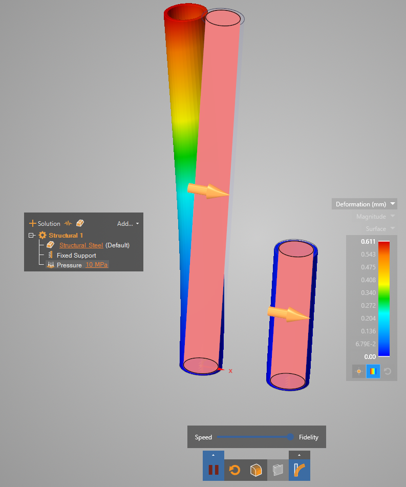
3 - The last model I've used to debug/investigate this behaviour is a simple straight pipe with only internal pressure and fixed at one end. The model should not deflect at all, only radial expansion. the element size is fixed to 1.5mm and the thickness is 8mm, so again the element size is small enough to capture any detail. An yet the longer the pipe the bigger the bending.
My understanding is that there is a problem on how Live is applying the pressure to the voxels. Not sure if you want to continue this this query here in the forum or we should deal with it outside it. Please let me know. I would like to find out what is happening here so I can advice my costumer on the best way to use the software.
Best Regards
Gabriel
🛈 This post originally contained file attachments which have been removed in compliance with the updated Ansys Learning Forum Terms & Conditions-
December 10, 2019 at 10:09 pm
Brian Bueno
Ansys EmployeeGabriel Arias
The developer I've been consulting with is currently out of the office. I will get back to you with an answer once I get his input.
-
-
January 7, 2020 at 9:41 am
garias
SubscriberHi Brian,
Any updates on this issue? I know it's been Xmas, but I have not seen any updates in the last 3 weeks.
-
January 7, 2020 at 3:25 pm
Brian Bueno
Ansys Employee
-
-
January 7, 2020 at 3:36 pm
garias
SubscriberThanks Brian,
I will test it and I will let you know if the issue is resolved.. Thanks for your reply
-
January 10, 2020 at 10:43 am
garias
Subscriber -
January 13, 2020 at 9:26 am
garias
SubscriberHi Brian,
Any updates on this issue. As I said, I've tried the new version and is not giving the correct results in the example above. What additional information do you need to debbug the problem?
-
March 10, 2020 at 3:55 pm
Brian Bueno
Ansys EmployeeGabriel Arias
Sorry for the delay. I see the issue you're referring to when I go to maximum fidelity for this model, but up to that point the results are OK I think. My minimum feature size was about 0.65 mm and the deformation was .136 mm. I will follow up with the development team to have this investigated because it is a bit strange.
Please keep in mind that Discovery Live is intended primarily for design exploration. The goal is to generate the results quickly to allow testing of multiple concepts. The trade off for this speed is accuracy.
For design validation and the highest accuracy, you should use Discovery AIM.
-
-
- The topic ‘Strange Behaviour as the fidelity is increased’ is closed to new replies.
-
6379
-
1906
-
1457
-
1308
-
1022
© 2026 Copyright ANSYS, Inc. All rights reserved.


