Hello,
I am working with Electronics desktop 2023R1 Maxwell 2D, trying to analize a permanent magnet BLDC motor. The permanent magnet that I am using for my model is a "injection molded neodymium magnet" and I am struggling with the setups and its results. I will try to explain what I wanted to perform with Maxwell 2D, what I did and results comparisons. This will be a bit long paragraph. I would like to get some help if there are anyone expirenced with similar model.
Background
I already have a physical motor that I can test and I am trying to compare between simulation and measured data.
To make simulation results realistic, I am trying to matching up the shape of magnetic flux as sinusoidal or trapezoidal form using plastic injection cylindrical type magnet.
Because permanent magnetic flux shape of this motor is trapezoidal.
Normally, in material set-ups on Ansys Electronics, I set the magnetization direction of a permanent magnet either radial (Cylindrical coordinates) or parallel (Cartesian coordinates) as pic below:

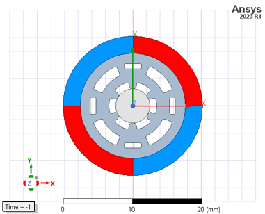
In the model, magnet separated by number of poles
With above set-up (Radial magnetize), No-load BEMF shapes looked as [Fig. A] while real sample measured BEMF shapes looked like [Fig. B].
Results shows both the shape and value of BEMF data was different.

[Fig. A] No load BEMF simulation results at 1000 RPM

[Fig. B] No load BEMF measured results at 1000 RPM
Questions

[Fig. C] Permanent magnet B-H curve

[Fig. D] Permanent magnet material
1. Double check on data input
My input data is following: Hc (#A) as coercive force Hcb, Br (#B) as residual induction and Mu (#C) calculated value using Hcb & Br & u0. Those values automatically goes into relative permeability, magnitude of magnetic coercivity from Mu (#C) and Hc (#A) respectively. Regardless of magnet shape, is there any error input on permanent magnet material set-ups?
2. Magnetize
Assuming my set-up was correct, to form magnetic flux as trapezoidal, I used parametric equations since Maxwell support mostly everything.
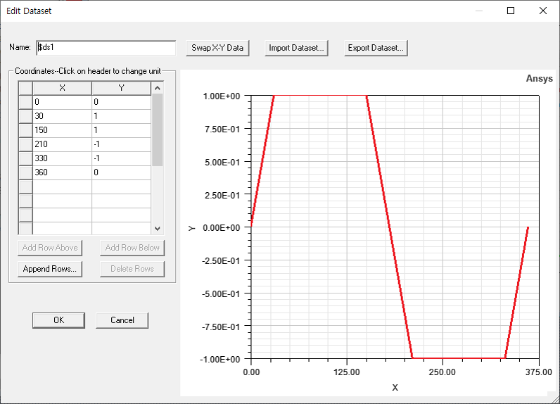
I made trapezoid graph on dataset (Project > Dataset) as shown [Fig. E]
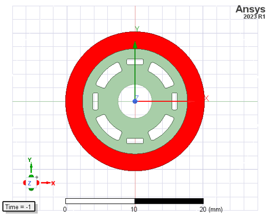
Using this dataset and internal function called “pwl_periodic”, I modified magnitude value from a single number to parametric equation. Also, I united the magnet model as single part as well (separated by number of poles à one single part)
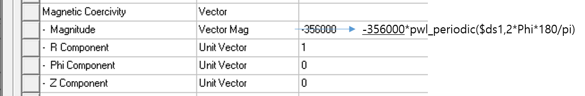
-Coordinate: cylindrical
-Magnitude: -356000*pwl_periodic($ds1,2*Phi*180/pi)
The results looked like [Fig. F] when I use magnitude as above equation. It shows BEMF shape pretty similar to real measurement; refer to [Fig. B]
")
[Fig. F] BEMF results using parametric magnitude (magnet)

[Fig. E] Data set
Question is: is this the right way to magnetize when the magnetic flux has specific periodic shapes?
3. Amplitude of magnitude value
Obviously, the higher amplitude creates the higher BEMF values. However, using given Hc value did not make the results similar to measured value.
-Magnitude: -356000*pwl_periodic($ds1,2*Phi*180/pi)
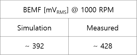
To make BEMF value similar to each other I had to somewhat increase scale value. Now, about 9 % error exist with respect to simulation results but I would like it to be less then 5 %.
Is there right way to select proper amplitude value?
4. Permeance coefficient of magnet
I believe one of the reason why existing gap between simulation and real measurement is a permeance coefficient of the permanent magnet. In my opinion, the Permeance coefficient has something to do with surface magnetic flux.
Is the Maxwell able to calculate the coefficient in any way? If so, is it possible to share simple manual?
Those quesitons are pretty self-related each other. Again, if any help on these problem, I would be really appreciated.
Thank you!