-
-
February 17, 2023 at 4:21 pm
Kili
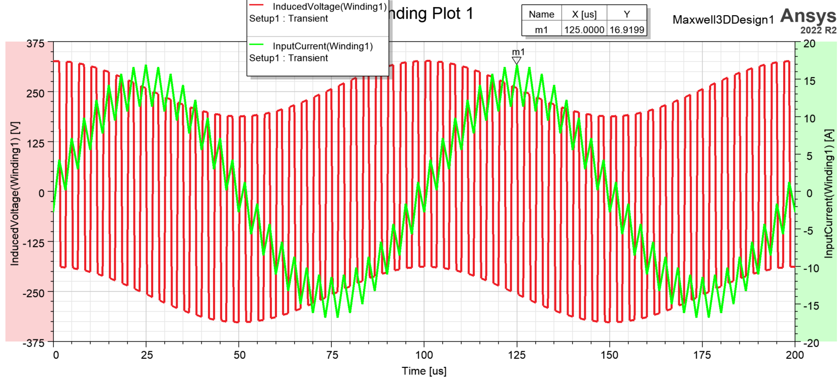
SubscriberHi everyone, I'm trying to simulate the losses in an inductor, I got a dataset as current excitations that came from an Excel file, here it is :
 As you can see, a maximum peak current is reach a first time at 25 us so the maximum losses should also be at this moment.
When looking at my Solid Loss results, I got this graph :
I don't understand why the maximum losses are reach at another moment. If anyone has an idea, maybe a problem in the setup analysis ? Thank you
-
February 22, 2023 at 1:44 am
HDLI
Ansys EmployeeHello Kili,
1). Could you check if you have other solid losses except for the inductor? Solidloss is total solid loss in the model.
We could check eddy effect, or integrate Ohmicloss in the inductor object in field calculator.
2). Addtionally, this solid loss would include the AC loss. Do you check if you have big AC effect on the inductor? The AC loss would not be proportional to I^2. Thanks.
Howard
-
- The topic ‘ANSYS Maxwell – Losses not realistic in inductor’ is closed to new replies.


- Hfss 3D pcb via capped and filled with epoxy
- AEDT Natural Convection with default correlation is failing solver initializatio
- Three-Phase Voltage Imbalances in dual stator electric generator
- Calc Error in Field Calculator after PyAEDT Analyze
- Co-simulation in Q3D, Icepak – meshing problem
- Classic Icepak – clarifications on Boundary condition
- Link the Circuit to 3D Terminals
- Rectangular Coil in Maxwell for WPT using solid block
- Magnetic Dipole moment calculation
- Integration lines or U Axis Line for circular and rectangular ports

-
4512
-
1494
-
1386
-
1209
-
1021

© 2025 Copyright ANSYS, Inc. All rights reserved.


