-
-
January 13, 2023 at 5:02 pm
Tom Grant
SubscriberHi there, I am trying to import a binary image into an FDTD simulation i am currently running, however every time i try to import this (I have tried with Binary Import and Image import) quality is lost from the image I want to import, and the resultant structure in my simulation. Please could you suggest how I can fix this?
Thanks.
-
January 13, 2023 at 6:18 pm
Guilin Sun
Ansys EmployeeBinary quality is lost? do you mean it chages the geometry such as hole sizes? you can modify the threshold for image import to change the refractive index. An alternative method is to create the binary object with script: https://optics.ansys.com/hc/en-us/articles/360034382754-Binary-spatial-data-Simulation-object
If the problem still exists, please give some screenshots and explain the procedures you followed.
-
January 17, 2023 at 4:41 pm
Tom Grant
SubscriberHi, please see reply below (I'm not sure if I replied to the correct message).
-
-
January 17, 2023 at 3:40 pm
Tom Grant
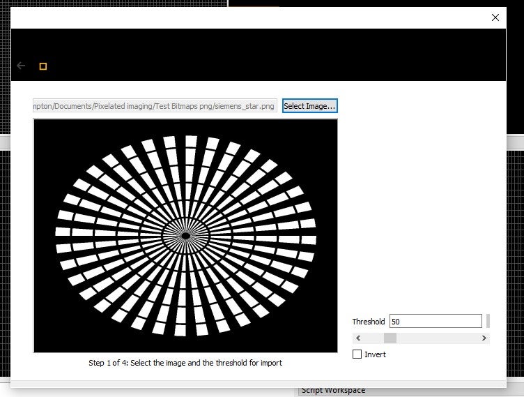
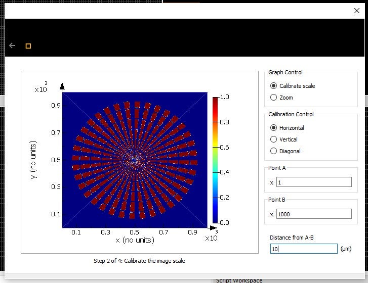
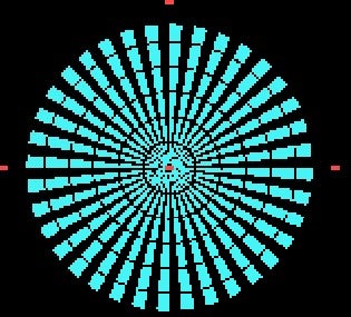
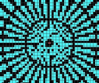
SubscriberHi, thanks for getting back to me. I do mean that binary quality is lost. I have attatched some screenshots to this message (when I follow the image import procedure). The first shows the target image (a 1000x1000 binary image, with desired pixel size in simulation 10nm - which is specified in the second screenshot). The third screenshot shows that this import maintains the quality of the desired image all the way down to the finer regions. The fourth and fifth screenshot is the result of this being imported into the simuation region (entire bitmap and zoomed in section where the problem occurs), where it is clear all information is lost. I have also tried to do this with the binary import function and i get the same result. I do not think it is a problem with the mesh since the smallest mesh size is also 10nm. Thanks.


-
January 17, 2023 at 5:05 pm
Guilin Sun
Ansys EmployeeIt is reasonable that the image is discrete such that it is not continuous. You may need to adjust the threhold carefully. 50% seems not the best.
-
January 17, 2023 at 5:09 pm
Tom Grant
SubscriberI have tried different threshold and still have the same problem. In the input image I use the image is also discrete but the step size of its is much smaller, meaning this central section has some structure,rather than being random. Even when I try importing this differently (using import binary) it still results in an extra level of pixelation which is not contained within what is imported.
-
-
January 17, 2023 at 6:32 pm
Guilin Sun
Ansys EmployeePlease try our online example image and see if you find the same issue.
-
January 18, 2023 at 12:43 pm
Tom Grant
SubscriberI have just tried this an it gave the same result. I did just notice on the page you linked in an earlier message it did have a note on image resolution (saying it was automatically low). However i have since tried fixing this in the graphical rendering tab as is suggested and this makes no difference to the image quality for me.
-
-
January 18, 2023 at 6:54 pm
Guilin Sun
Ansys Employeegraphical rendering is only for display.
FDTD uses rectilinear building blocks to construct the geometry. Even though you have an ideal disk or sphere, the FDTD will reconstruct them into small rectangles. Thus for circular sectors, it will be discontinuous.
In addition, the import has limited resolution by default. Maybe the key is to increase it. However, different from the built-in geometry, the import may require much more memory. This might be the reason it has limited resolution. I would suggest that you file a feature request:
New Feature vote: Vote new features, and file your feature request
-
- The topic ‘Importing binary images’ is closed to new replies.


-
5044
-
1754
-
1387
-
1248
-
1021

© 2026 Copyright ANSYS, Inc. All rights reserved.


