Ansys Assistant will be unavailable on the Learning Forum starting January 30. An upgraded version is coming soon. We apologize for any inconvenience and appreciate your patience. Stay tuned for updates.
Electronics

Electronics

Topics related to HFSS, Maxwell, SIwave, Icepak, Electronics Enterprise and more.

Single-Port Model/Circuit Element on Coax in HFSS

    • Dustin Pieper
      Subscriber

      Greetings,

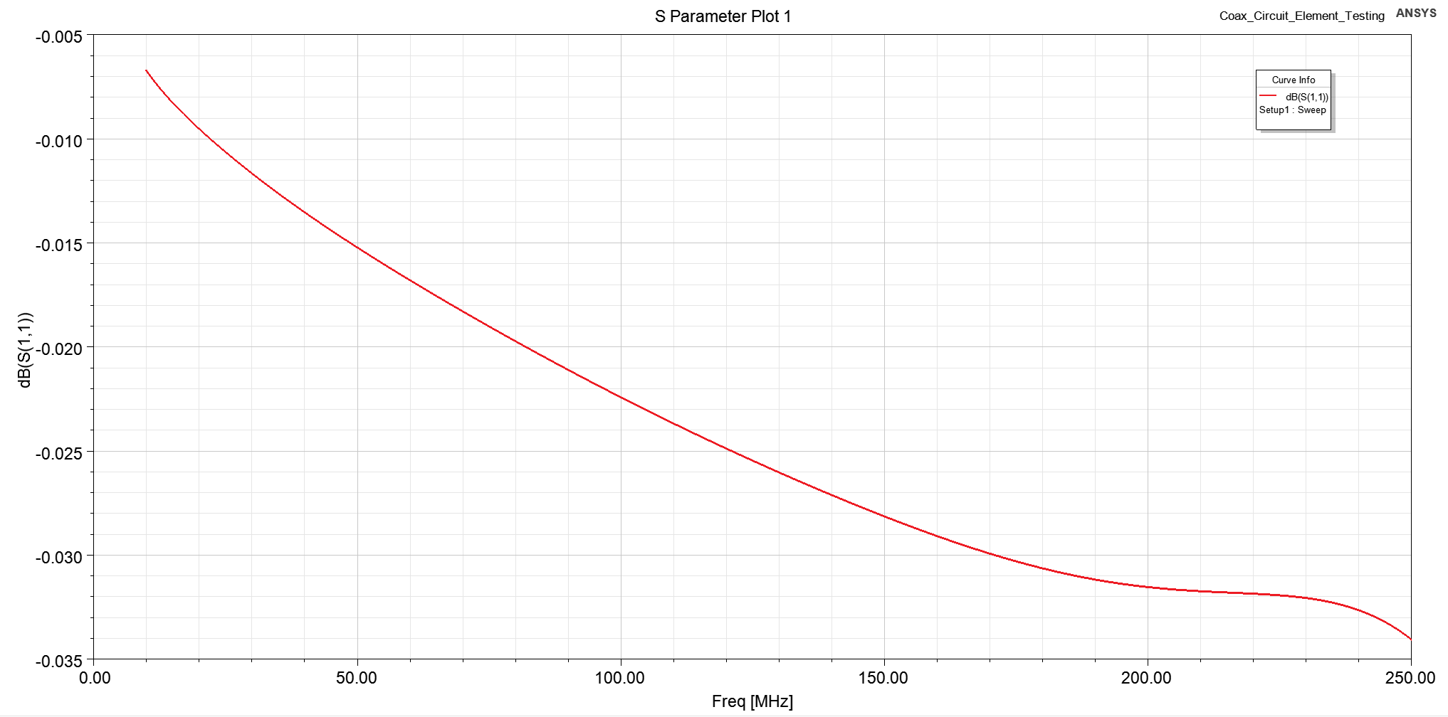
      I have been attempting to use HFSS's Single-Port Model feature (covered in Ch 19 of the help manual) in a simulation to represent a complex Circuit Element for a system that I am simulating. However, when I apply this tool to a coaxial port, I have not been getting reasonable behavior, and instead the system is just behaving as an open circuit. I've been able to get a Single-Port Model to work on a microstrip format, so I believe I'm otherwise using the feature correctly. Is there something I'm missing in the Circuit Element behavior?

      An example coaxial simulation is provided below for reference:
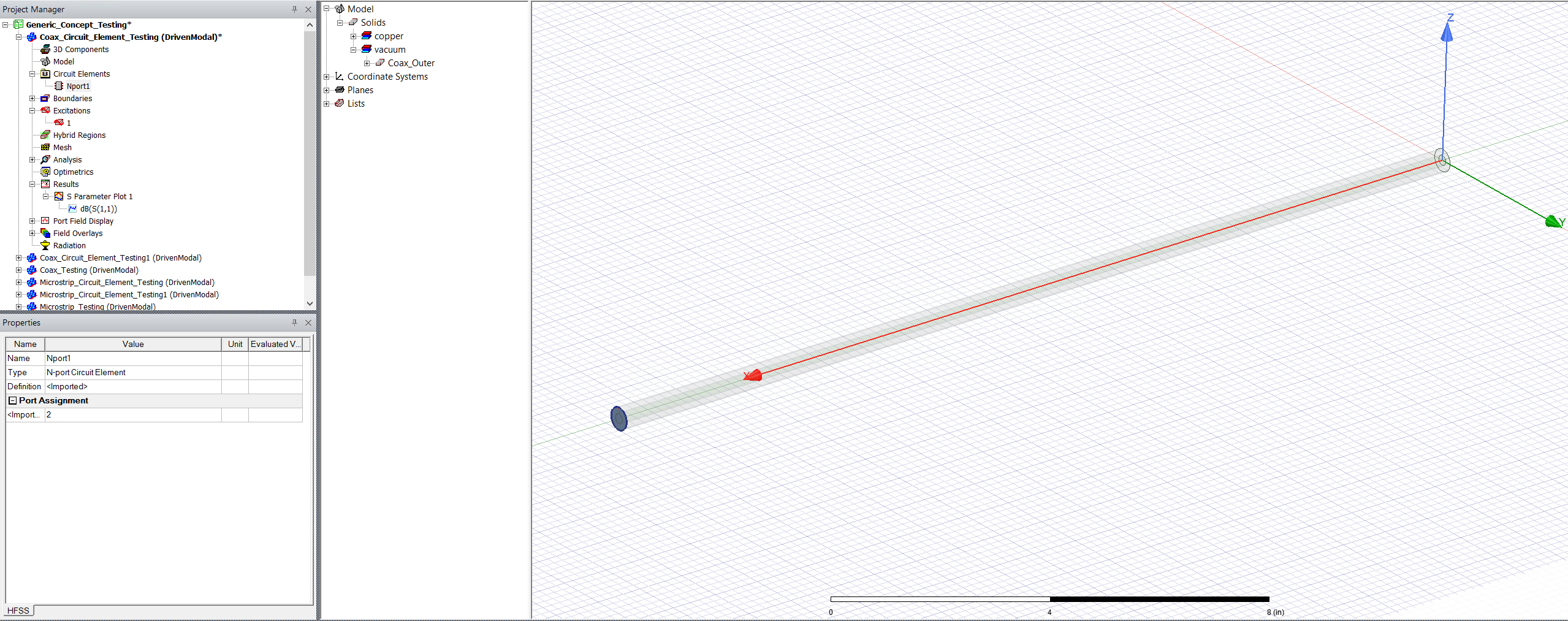
      I'm feeding the other end with just a simple lumped port. I've simulated this geometry with lumped ports on both ends to make sure the model is valid, so that's not the issue.

      Here's the example s1p file I've used to define the Circuit Element for the Single-Port Model:
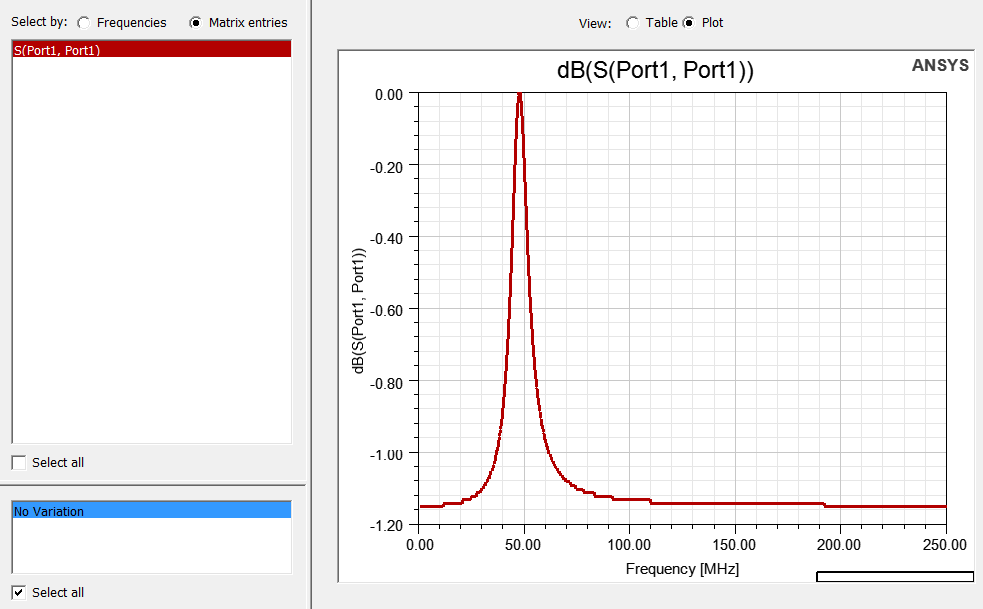
      Since this is just a simple matched coax line, the S11 of my lumped port should basically just look like that, right? However, instead it just looks like a mostly open circuit. Observe:
      I've also seen that the E-fields at the Circuit Element definition boundary at the end of the coaxial line don't conform to the expected TEM distribution (while they do for the feed at the other end), which leads me to believe that there is an extra definition that I need to do.

      Any advice or help would be appreciated!

    • Praneeth
      Ansys Employee

      Hi Dustin,

      Thank you for reaching out to the Ansys Learning Forum and your patience is much appreciated.

      As it is a long time since the time of your post, were you able to progress in your analysis, or still facing the same issue?

      Did you try simulating different types of responses with the touchstone file? If so, were you able to get different results for different responses?

      Best regards,
      Praneeth.

    • Dustin Pieper
      Subscriber

      I eventually found a workaround by essentially modeling a coax-to-microstrip transition section and then defining the port at the end of the microstrip, but it's not particularly ideal. Last I tested, using coaxial ports with circuit elements is still not working.

    • Praneeth
      Ansys Employee

      Hi Dustin,

      If you are interested then you can try simulating the single port circuit response with different touchstone files (with variations in the matching frequency and the level of matching) and see if you are getting the same result or different results. In this way, it may be possible to identify the cause of this issue.

      Best regards,
      Praneeth.

Viewing 3 reply threads
  • The topic ‘Single-Port Model/Circuit Element on Coax in HFSS’ is closed to new replies.
[bingo_chatbox]








