-
-
October 16, 2022 at 7:03 pm
-
October 16, 2022 at 7:33 pm
peteroznewman
SubscriberApply a Force or Pressure to any surface that experiences a harmonic input load. Enter the amplitude of that force or pressure in the Details and the Harmonic Response analysis will sweep that amplitude from the start frequency to the end frequency you specified under Analysis Settings and calculate the harmonic response over the entire structure for displacement, velocity, acceleration as well as stress if you set the corresponding output requests under Analysis Settings.
-
October 18, 2022 at 5:18 pm
javat33489
SubscriberThanks for the answer.
I'm a little confused. But already understood.
I have two questions.
- How is the damping factor calculated? How to define it? Or is it usually 1-2%?
- 2. I want to transfer the load from the pump to the pipe. I have a tabular data that is PERMISSIBLE VIBRATION AMPLITUDE 60 microns. Can I set this load only using displacement? Or should I make this load a function of the frequency? And how to do it?
-
-
October 17, 2022 at 8:42 am
Erik Kostson
Ansys EmployeeAlso see our free online courses on this topic and on others that are relevant (e.g., Getting Started with Mechanical, etc).
/courses/index.php/courses/harmonic-response-analysis-in-ansys-mechanical/
A full list of our structural related courses can be found here:
/courses/index.php/structures/
All the best
Erik
-
October 18, 2022 at 5:12 pm
javat33489
SubscriberThanks a lot! It helped me. But there are a couple of questions.
-
-
October 19, 2022 at 2:08 am
javat33489
SubscriberThanks for the answer.
I'm a little confused. But already understood.
I have two questions.
- How is the damping factor calculated? How to define it? Or is it usually 1-2%?
- 2. I want to transfer the load from the pump to the pipe. I have a tabular data that is PERMISSIBLE VIBRATION AMPLITUDE 60 microns. Can I set this load only using displacement? Or should I make this load a function of the frequency? And how to do it?
-
October 19, 2022 at 10:43 am
peteroznewman
SubscriberIf the structure has been built, one method damping can be measured is by using an accelerometer and an impact hammer using the decay of the transient. See this article: https://en.wikipedia.org/wiki/Logarithmic_decrement
If the structure has not been built, then use values established in the literature. A welded steel structure is going to have different damping parameters than a bolted steel structure or a concrete structure.
Please show the tabular data that is PERMISSIBLE VIBRATION AMPLITUDE 60 microns. Is that a statement about the pump or the pipe?
When I read PERMISSIBLE VIBRATION AMPLITUDE 60 microns, that sounds like a requirement. After you have applied the unbalanced force caused by pump, you would plot a Displacement result and check that no part of the structure had a vibration amplitude exceeding 60 microns.
The pump specification might have a requirement on the maximum unbalance of the rotor calculated from the mass m of the rotor and the radius r of the center of mass from the rotational axis. You can calculate the force F amplitude as a function of rotor angular velocity w using the formula F = mr(w^2).
-
October 19, 2022 at 4:40 pm
javat33489
Subscriber>>If the structure has not been built, then use values established in the literature. A welded steel structure is going to have different damping parameters than a bolted steel structure or a concrete structure.
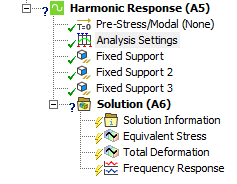
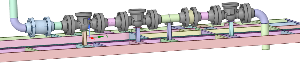
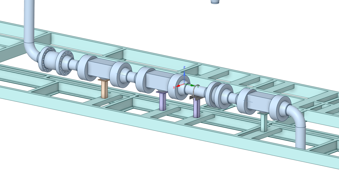
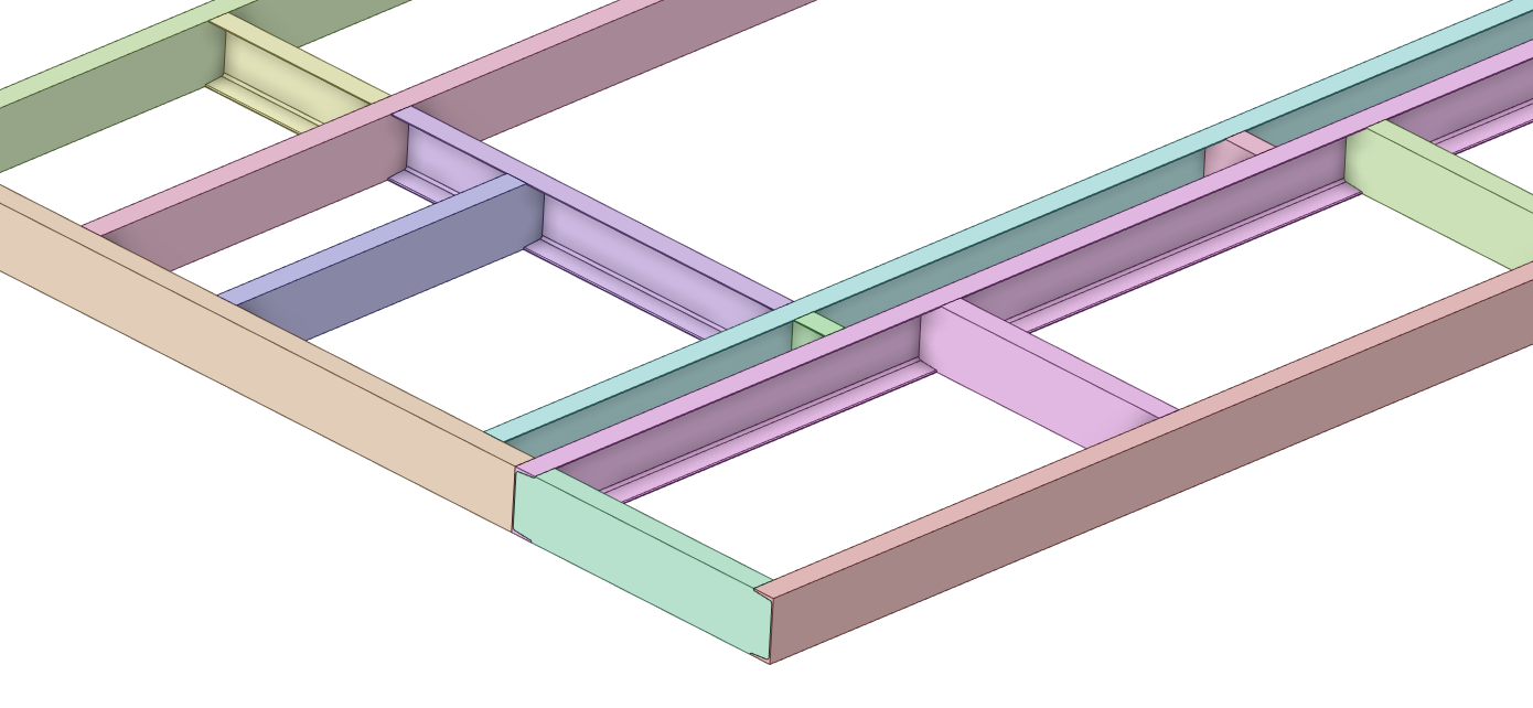
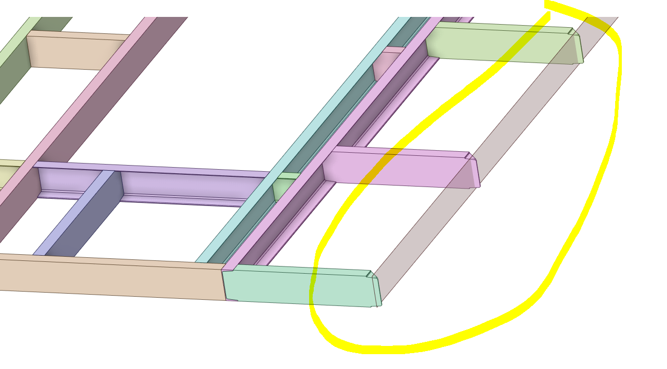
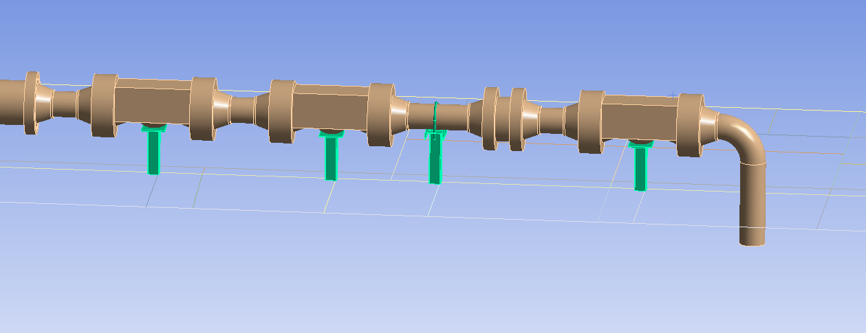
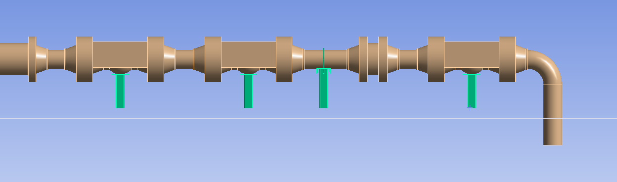
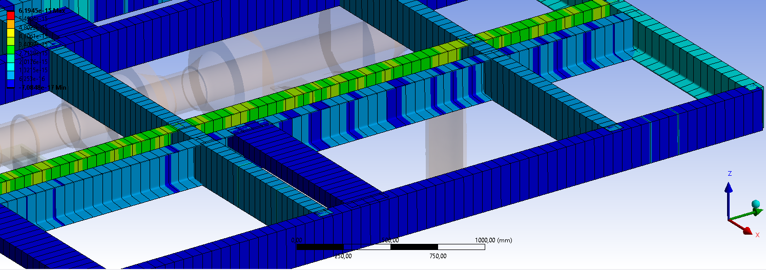
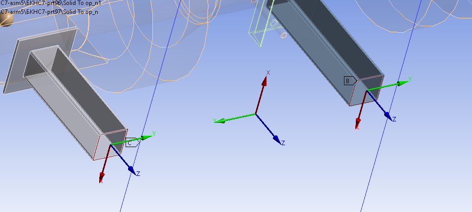
my design is a pipe that comes from the pump and is supported by metal structures:
>>Please show the tabular data that is PERMISSIBLE VIBRATION AMPLITUDE 60 microns. Is that a statement about the pump or the pipe?
this approval is for the pump, it is indicated in the documentation for these pumps.
Can i use displacement to apply 60 microns? without converting it to a function?
>>The pump specification might have a requirement on the maximum unbalance of the rotor calculated from the mass m of the rotor and the radius r of the center of mass from the rotational axis. You can calculate the force F amplitude as a function of rotor angular velocity w using the formula F = mr(w^2).
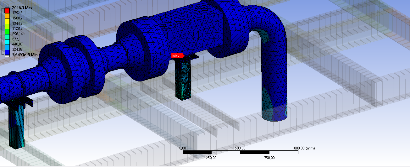
There is no data on the pump yet, it has not yet been manufactured. But the customer wants to make a calculation. 60 microns is all there is from the boundary conditions.
-
-
October 19, 2022 at 8:07 pm
peteroznewman
SubscriberYes, you can use a displacement B.C. of 60 microns on the surface the pump mounts to. You might want to run that displacement in 3 different directions. The 60 microns will be used in a frequency sweep from the lowest to the highest frequency in your analysis. Note that the acceleration that this displacement B.C. creates goes up as the square of the frequency.
-
October 20, 2022 at 2:29 am
javat33489
SubscriberThe pump will stand on an independent concrete foundation slab. Pipes will go from the pump, which will stand on the structure as in the picture that I sent. I will apply 60 microns only to the pipes where they attach to the pump. Should I apply 60 microns in 3 XYZ planes? 60 microns per plane?
I will analyze the pipes and whether they transmit vibration to the metal frame of the base
-
-
October 20, 2022 at 10:49 am
peteroznewman
SubscriberYes, you should apply the 60 microns to the flange of the pipe in three separate analyses: X, Y and Z axis.
-
October 20, 2022 at 3:59 pm
javat33489
SubscriberThanks a lot.
A couple more questions please.
1. The geometry of the pipe and metal base is very complex. I had to greatly simplify the geometry of the pipe, remove the holes on the flanges, simplify the valves, remove fasteners and chamfers and fillets on them. I made the pipe a single body in the space claim. I set the mass of the sliders through point mass in order to save the masses after changing the geometry. Is this allowed? Will this affect the accuracy of the calculation? Th frequency modes will not change much.
It was like this
it became so
2. How else can you forgive geometry? I ended up with 500,000 grid items. I have a powerful PC, 8 cores, 32 GB of RAM, but this is not enough, a memory error appears. I tried virtual topology, it didn't help either.
-
-
October 20, 2022 at 11:35 pm
peteroznewman
SubscriberThe structure the pipes sit on looks like it is made from steel beams of various cross-sections. In SpaceClaim, use the Midsurface button on the Prepare tab to replace the solid model of the structure with a surface model.
It looks like there are still some bolt heads on the flanges. Get rid of those.
You must end up with the same mass in the idealized geometry as you have in the original geometry. You can do that by adjusting the density of the material to make up the missing mass.
What is in the pipe, is it a gas or a liquid? If it is a liquid, you need to include the mass of the liquid.
-
October 21, 2022 at 2:00 am
javat33489
Subscriber>>The structure the pipes sit on looks like it is made from steel beams of various cross-sections. In SpaceClaim, use the Midsurface button on the Prepare tab to replace the solid model of the structure with a surface model.
In this case, the pipes will be solid and the base surfaces?
>>You must end up with the same mass in the idealized geometry as you have in the original geometry. You can do that by adjusting the density of the material to make up the missing mass.
Thanks for the advice. I achieved mass with Point Mass in the Geometry section of the boundary conditions problem.
>>What is in the pipe, is it a gas or a liquid? If it is a liquid, you need to include the mass of the liquid.
There is water and pressure. Will I need to set pressure? Can I take into account the mass of water also using Point mass? Can I select the entire pipe (without valves) and assign a single point mass to it with water?
Thank you!
-
-
October 21, 2022 at 11:36 am
peteroznewman
SubscriberYes, the pipes will be solid and the base structure will be surfaces.
A simple way to account for the mass of water is to use a Distributed Mass. Select all (or most) of the internal surfaces of the pipe as the scope of the Distributed Mass. SpaceClaim can be helpful in determining the volume of water in the pipe by using the Volume Extract button. Multiply the volume by the density to get the mass.
-
October 21, 2022 at 4:55 pm
-
-
October 21, 2022 at 6:44 pm
peteroznewman
SubscriberDoes the C-channel section have a uniform wall thickness, or are the short side ribs tapered?
Midsurface only works on parallel faces, so you can't capture tapered ribs. You can convert the channel to a Beam model, which will replace the solid body with a beam with the correct cross-sectional area properties. Beam elements are a higher level of idealization than Shell elements. If you want to use Shell elements, you won't use the Midsurface button, you will pick the three outside faces of the C-channel and do a Ctrl-C, Ctrl-V to create the surfaces to mesh. You will manually assign a thickness to those surfaces in Mechanical. The tapered ribs will be assign a constant wall thickness, like the average between the base and the tip of the rib.
You can assign the 10 MPa internal pressure in a Static Structural model and feed the Solution cell of that into the Setup cell of the Modal analysis. This will cause the stiffening that the pressure causes to the pipe to be taken into account.
-
October 22, 2022 at 9:50 am
javat33489
SubscriberThanks for answers.
I also thought about extracting the profile of the metal base into the beams. If the base is in the form of beams and the pipes are solids, will this be ok? Unfortunately, the profile has a flat only vertical wall, the horizontal walls are upper and lower with a bevel.
>>You can assign the 10 MPa internal pressure in a Static Structural model and feed the Solution cell of that into the Setup cell of the Modal analysis. This will cause the stiffening that the pressure causes to the pipe to be taken into account.
So my harmonic calculation by the superposition method will have three modules:
- Static structurtal where I will apply pressure inside the pipes.
- Modal - natural frequencies
- Harmonic response - forces on the pipe where the pump is connected.
-
-
October 22, 2022 at 10:28 am
peteroznewman
SubscriberYes, you can have a beam model for the supporting structure.
Yes, this analysis will have 3 modules.
-
October 22, 2022 at 5:37 pm
javat33489
SubscriberThanks for answers. I'll test, later I'll write how it went.
-
-
October 23, 2022 at 10:20 am
javat33489
Subscriber>>Yes, this analysis will have 3 modules.
Should I also immediately set the point mass for the changed valves in static srtuctural?
-
October 23, 2022 at 11:47 am
peteroznewman
SubscriberWhat changed values are you talking about in Static Structural?
What does the point mass represent?
-
October 23, 2022 at 12:05 pm
-
October 23, 2022 at 12:10 pm
javat33489
Subscriber>>What changed values are you talking about in Static Structural?
What does the point mass represent?
I wrote earlier that I changed the design of the valves, removed all unnecessary (bolts, nuts, etc.). Now, when calculating, I specify their mass separately using the Point Mass tool. So that the calculation takes into account the correct weight of the valves. Earlier, we discussed that there is pressure in the pipes and you advised me to set the pressure through the Static Structural module, then transfer everything to modal analysis, after which everything will go to harmonic analysis. My question is this. Is the Point Mass set only at the first stage in Static Structural (weight of pipes with water and exact weight of gate valves)? It's enough?
-
-
October 23, 2022 at 1:07 pm
peteroznewman
SubscriberThe Static Structural model has all the mass in it. No mass can be added just for Modal. I thought you already put in the point masses the make the idealized valves the correct mass, so I was confused by the question.
Use a Fixed Joint to connect a face on the solid body to a vertex or node on the beam model.
-
October 23, 2022 at 3:08 pm
javat33489
Subscriber>>The Static Structural model has all the mass in it. No mass can be added just for Modal. I thought you already put in the point masses the make the idealized valves the correct mass, so I was confused by the question.
So I'm right? I specify all masses in Static Structural.
-
-
October 23, 2022 at 5:02 pm
peteroznewman
SubscriberYes, that is what I just said.
-
October 24, 2022 at 5:53 pm
-
-
October 24, 2022 at 8:08 pm
peteroznewman
SubscriberPlease show the Fixed Joint that goes from the bottom of the solid vertical stand to a set of nodes on the beams.
-
October 25, 2022 at 6:33 pm
-
-
October 25, 2022 at 11:53 pm
peteroznewman
SubscriberYou have scoped it to the entire Edge. It would be better to scope it to the nearest single Node on the line body.
-
October 26, 2022 at 6:19 pm
javat33489
Subscriber>>Node on the line body
Sir, this is not working in workbench. No nodes can be connected to a line or surface either in contact or in a joint(
-
-
October 26, 2022 at 7:20 pm
peteroznewman
SubscriberPick a Node and make a Named Selection. A joint can use a Named Selection.
-
October 30, 2022 at 11:54 am
-
-
October 26, 2022 at 8:16 pm
javat33489
Subscriber>>Pick a Node and make a Named Selection. A joint can use a Named Selection.
Sir, this is not working
-
October 30, 2022 at 2:08 pm
peteroznewman
SubscriberChange Applied By from Remote Attachment to Direct Attachment
-
November 2, 2022 at 4:34 pm
javat33489
SubscriberThanks it works. This only works for one node.
-
-
- The topic ‘Harmonic Response’ is closed to new replies.
-
3762
-
1333
-
1168
-
1090
-
1014
© 2025 Copyright ANSYS, Inc. All rights reserved.