TAGGED: ansys-maxwell-2d, core-loss, material, torque-calculation
-
-
September 24, 2022 at 5:44 am
JUNAED HOSSAIN
SubscriberIn 2D finite element permanent magnet motor design does the Moving1.Torque equal to the output torque (shaft torque). I have energised the windings with external circuit like figure 1 and defined the stator and rotor material characteristics with stacking factor , stacking direction and lamination like figure 2.
figure 1
figure 2
-
September 28, 2022 at 3:14 pm
Navya Chode
Forum ModeratorHi junaed,
Moving Torque is the electromagnetic torque. If the mechanical loss is small and the core loss effect is negligible or disabled then both moving torque and Shaft torque should be close to each other.
Regards,
Navya
-
September 28, 2022 at 4:07 pm
JUNAED HOSSAIN
SubscriberHi Navya. Thanks for your response. In the simulaton I have set coreloss in stator and rotor as shown in figure 1 .For the motor of 1kW BLDC supplied by 48 Volt supply at 2800 rpm speed the steady average core loss is 42.3639 Watt as shown in figure 2. At 2800 rpm the steady average moving torque is 3.547 Nm as shown in figure 3. What will be my shaft torque and output power in such case?
figure 1
figure 2
figure 3
-
September 28, 2022 at 4:28 pm
Navya Chode
Forum ModeratorCalculate the power from the moving torque and speed and subtract the core loss from it to get the shaft power.
Remember that you still did not subtract the friction, windage and mechanical losses from it.
Regards,
Navya
-
September 28, 2022 at 5:35 pm
JUNAED HOSSAIN
SubscriberThanks Navya. I am attaching a screen shot of some calculations regarding loss and efficiency calculation of motor and inverter. As I have mentioned earlier that I am exciting the windings with external circuit as shown figure 1 of my original post. I am trying to calculate the total loss and efficiency of motor and inverter. I have not considered mechanical loss (friction and windage loss) yet as I can not find the mechanical loss value like coreloss and solid loss. I am guessing it is an assumed value.Kindly let me know if there is any way to calculate this loss in maxwell 2D simulation. Anyway can you look into the figure below and verify if the calculations are correct? My main confusion lies with the inverter loss as it seems to be very high wherease I have specified values for voltage drop across switch and diode to be 0.7 Volt. I would be grateful to you if you provide some feedback on the calculation shown below.
If you like you can download the excel file from the Google_drive_link
Sincerely hope to have your response in this issue.
Junaed
-
September 29, 2022 at 2:01 pm
HDLI
Ansys EmployeeHello Junaed,
If the inverter's efficiency is 92.4%, I would accept this value and it makes sense.
However, please check manufacture data of switch and diode. Maxwell external circuit just provides ideal mode for them.
HDLI
-
April 10, 2023 at 11:51 am
Sampath kumar A V N
SubscriberHello Junaed,
I am working on the synchronous reluctance motor design,currently using current excitation for windings.I would like to implement voltage excitation so as to observe the current variation with loads.I request you can you please share the information how to do this.It would be really helpful to my research.
-
- The topic ‘
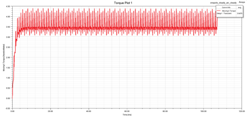
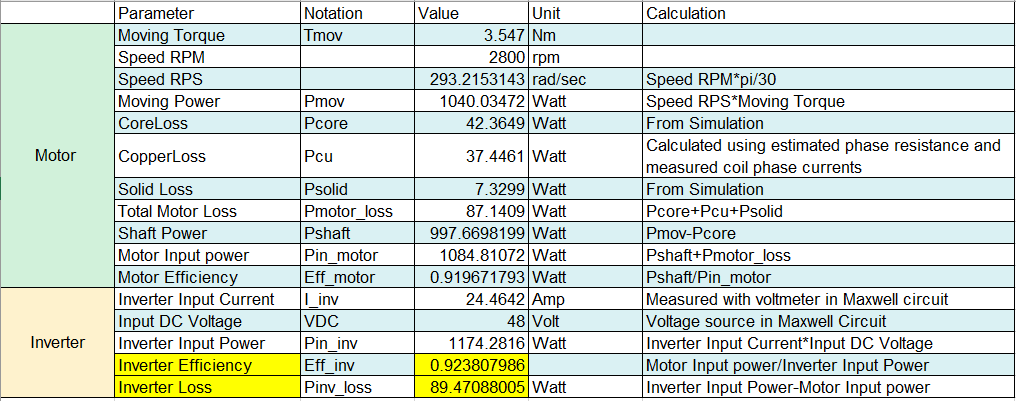
Is the Moving1.Torque is the output (shaft) torque ?’ is closed to new replies.
-
6450
-
1906
-
1457
-
1308
-
1022
© 2026 Copyright ANSYS, Inc. All rights reserved.


