We’re updating our badges platform. Badge issuance is temporarily paused, but all completions are being recorded and will be fulfilled once the platform is live. Thank you for your patience.
LS Dyna

LS Dyna

Topics related to LS-DYNA, Autodyn, Explicit STR and more.

Multi Surface Body Model Contact Definition

    • shervinjoses
      Subscriber

      Iam working on project in which the geometry is modeled as a surface/shell. I started with a solid model then used mid-surface function. The Issue that I encountered while working with surfaces/shell elements is that establishing contact between the surface parts seems confusing 

      While using mid-surface function on solid model parts that are in contact creates a gap between the parts as there is no thickness to the parts anymore and defining contacts between these parts is confusing. Inorder to get around this problem I used two methods:

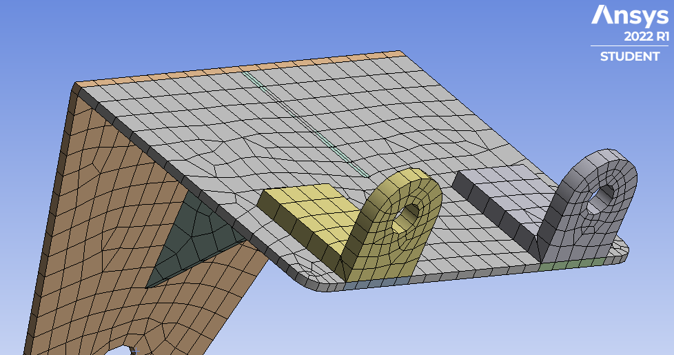
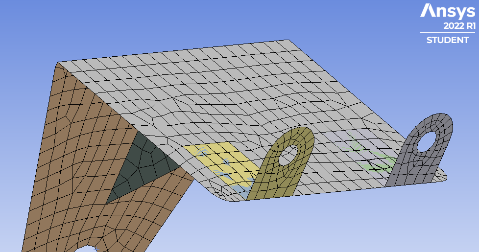
      1. Using Surface extends on the model to bring the surface edges in contact with another surface, so there is no gap between the parts anymore. Issue that I found with this method is that when I meshed the surfaces thickens as per the specified thickness and surface seems overlapping which quite seem right.

      Drawback:

      a) This method can only be used to fill the gap between the two surface bodies that are perpendicular to each other, doesnt work for surfaces parallel to each other.

      b) Extending surfaces causes change in geometry (not a lot)

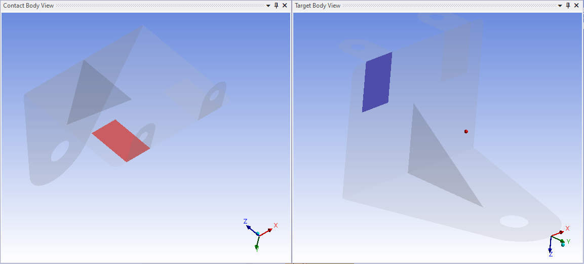
      2. Defining manual contacts between the surfaces and increasing the maximum offset value to the distance between the two surfaces (gap).This method seems to work for every case, but dont know if this method overconstrains the model from deforming, cause maximum offset value is huge and can link with parts in the way. Will the parts able to move towards the surface across gap ?

      Is any of the methods mentioned above correct way to tackle this problem. Is there any other way define to contacts  between two suface bodies 


      Images that are used is from an external source:

      https://www.youtube.com/watch?v=WmStCstAd78&t=689s

    • peteroznewman
      Subscriber

      With thickness turned on, you can see the effect of the offest to Top or Bottom of the shell elements.

      All the surfaces are on the same plane.

      The thin part surface was imprinted with the thick part outline to make a clean edge for the contact.

      ANSYS2022R1 archive: https://jmp.sh/FHR1SvH

    • shervinjoses
      Subscriber


      Thank you for your comment,

      1. Sorry, I forgot to specify that I am working on explicit dynamics which prefers only surface offsets to the middle

      2. From the Image 1 that you posted, it seems like the middle stiffner part is overlapping the L-bracket when surface is thickened, is that ok?. When we offset the surface to a particular direction how does the program see, is it mathematical or its just a visual graphics.

      a) if its mathematical then the overlapping thickened surface creates an issue in the behaviour of the simulation

      b) if its visual then it doesn’t matter in which direction we thicken the surface to, only thing that matter is the base surface body, right?

      3. From the images that you posted it seems like you started with a surface body model in which all parts are in contact and you thickened the surfaces in different directions to avoid overlapping. If you’re able to work with only mid-surfaces (in explicit dynamics), ie., the surfaces can be thickened only using the middle option, definitely there would be a gap right !, in that case how can I define contacts?

      Especially when working with huge asembly of surface bodies, its difficult memorize in which direction each surface should thicken to.


    • peteroznewman
      Subscriber

      Turning the thickness display on is mostly visual, there is no physical overlap. When you turn thickness display off, you can see the middle stiffener just touches the plane of the L-bracket. The middle stiffener shares nodes with the L-bracket, so no contact is required.

      The thickness display shows you mathematically that the element stiffness formulation will incorporate the offset. Bending is slightly affected by the offset. If the L-bracket was offset to the Top, then the center stiffener would not need to be extended. When the L-bracket is offset to the Bottom, the center stiffner is extended, which increases the mass of that bracket, so that is another mathematical effect of offset.

      Yes, I started with surfaces that were on the same plane and customized the offset direction to get the visual appearance correct, which also provided a mathematically correct stiffness of the structure.

      Since you are working in Explicit Dynamics where shell offsets are not supported, you have to use midsurfaces and contact to connect one shell to another across the two half thicknesses when the planes are parallel. You have to make sure the Pinball radius is large enough to cross that gap.

    • shervinjoses
      Subscriber


      Yeah, It makes sense, thank you for clarifying, it really helps. There’s one thing that slightly confuses me is what do you mean by the middle stiffner share nodes with the L-bracket, so no contact is required. Is it modelled as a single surface body? or did you define some kindof mesh connection or used shared topology. When you model two surface bodies in contact, it doesn’t really have to share nodes and if you didn’t define a contact between two surface bodies there wouldn’t be an interaction between the two bodies or am I missing something?


    • peteroznewman
      Subscriber

      I used Shared Topology by clicking the Share button on the Workbench tab in SpaceClaim to get a mesh with shared nodes.  I can get the same effect by using a Mesh Connection in Mechanical.

Viewing 5 reply threads
  • The topic ‘Multi Surface Body Model Contact Definition’ is closed to new replies.