TAGGED: ansys-maxwell-electronics, faradays-law, maxwell, rogowski
-
-
May 17, 2022 at 12:07 pm
mancini.alessio86
SubscriberHi guys,
I am trying to simulate a rogowski coil in ANSYS Maxwell through a simple modelling of the conductors. I would like to know the voltage that it is induced in the rogowki coil if I vary the current in the other conductors.
It seems that Maxwell overestimate the results.
Anyone has some ideas? Shoudl I switch off "Eddy current effects".
Cheers,
May 18, 2022 at 12:29 pmMay 23, 2022 at 11:09 ammancini.alessio86
Subscriber
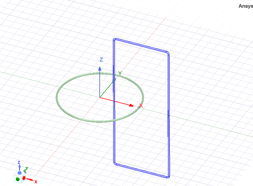
thanks a lot for answering me. Basically the geometry is the one attached below. The rogowksi is the blue one.
Basically I am varying the current in the conductor in grey, and I see in "Transient" with "Eddy effects" switched on which is the current induced in the conductor.
I am not sure if this is the right way to do it. I am trying to also mimic the behaviour of the rogowksi by adding the terminal in one of the cross sectional area on the (x-y) plane and using a winding controlled by tension and just giving the resistence of the coils.

If I use the eddy effects the current is quite different from the theoretical behaviour, but if I use the windings it is even lower.
I hope you can give me some tips/advices.
Cheers
Viewing 2 reply threads- The topic ‘Rogowksi Coils’ is closed to new replies.
Innovation SpaceTrending discussionsTop Contributors-
5874
-
1906
-
1420
-
1306
-
1021
Top Rated Tags© 2026 Copyright ANSYS, Inc. All rights reserved.
Ansys does not support the usage of unauthorized Ansys software. Please visit www.ansys.com to obtain an official distribution.
-
