

-
-
March 30, 2022 at 6:18 pm
murali666
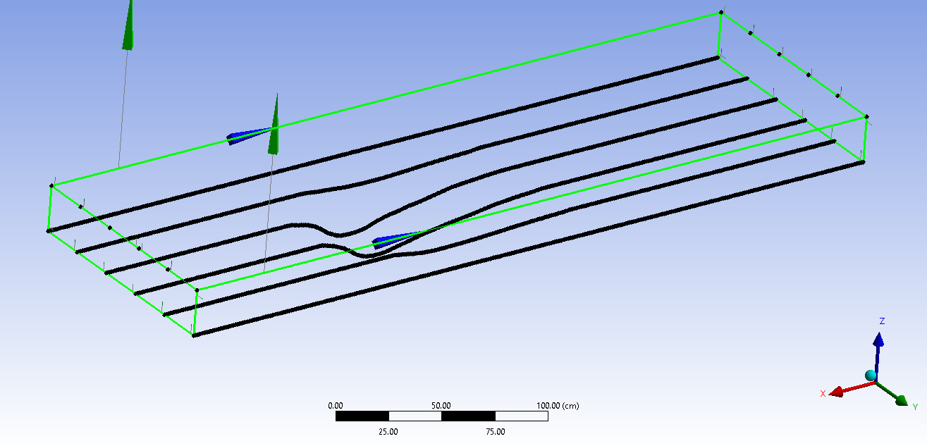
SubscriberI have a coordinates (X,Y, and Z) of all points as shown below. I have a lot of points in between the black lines displayed below. I imported only few points to avoid clumsiness.
March 31, 2022 at 3:32 amKeyur Kanade
Ansys EmployeeYes, you are on correct path. Once you create surfaces, please use Sew command.
Please go through help manual for more details
Regards Keyur
How to access Ansys Online Help Document
Guidelines on the Student Community
March 31, 2022 at 7:09 amSubscriberThank you for your response.
I combined all the surfaces and generated a solid body using the sew command.
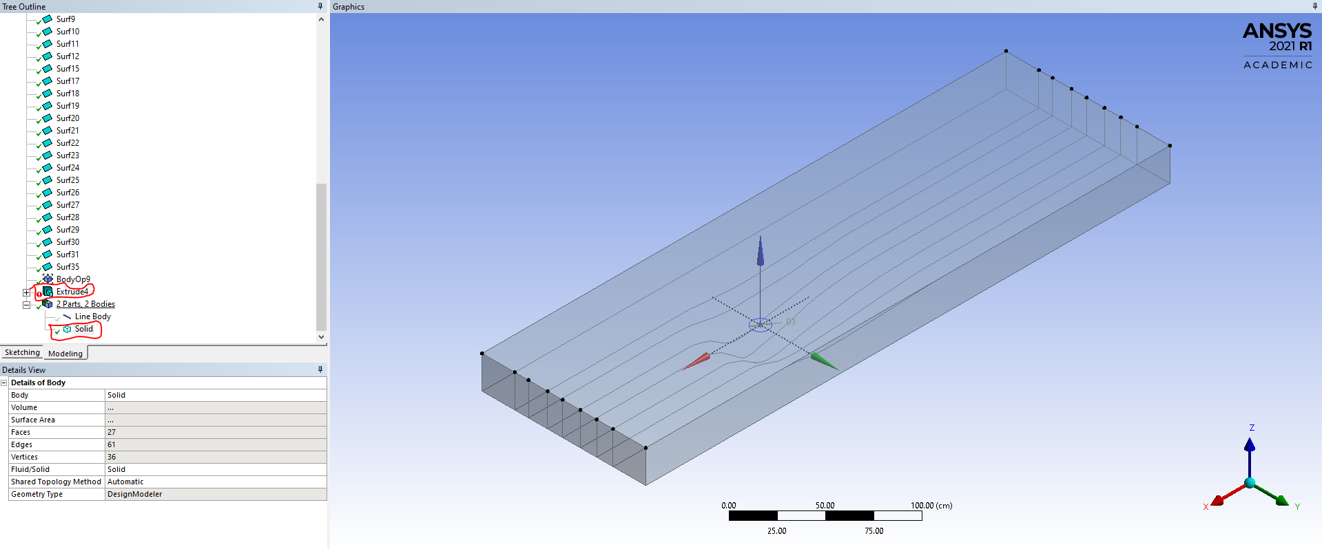
But why this solid is looking like hallow, why it is not looking like actual solid body like below.
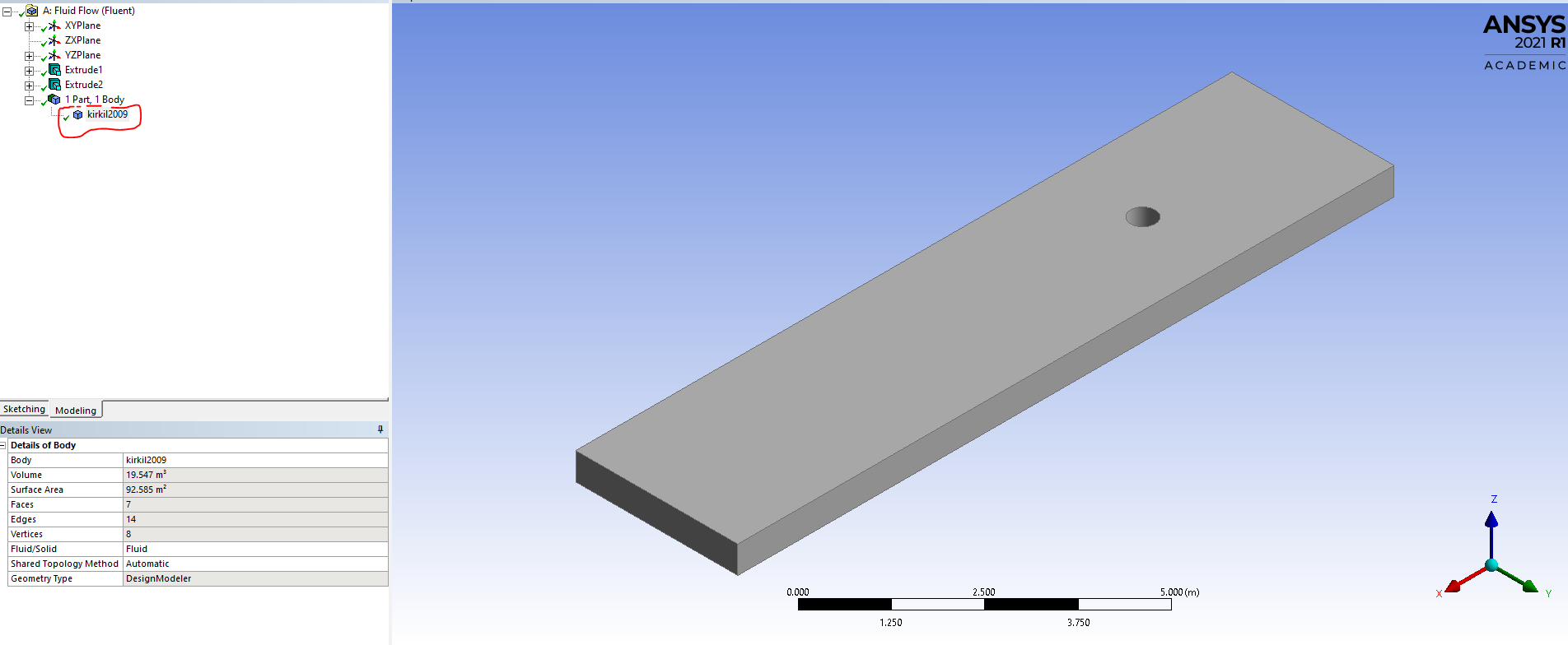
I want to create a circular hole at center (as shown in circle in above figure) like as shown in the below figure. In below figure, first I created a circle on the bottom plane and extruded it and selected cut material option in during extrude operation. I tried to do the same in the above case, but it didn't worked.
Please help in creating the circular hole in the above figure and explain me why both the solids are looking different.
March 31, 2022 at 12:08 pmAnsys EmployeeTo look like solid - change display option. Use view - shared exterior
To cut hole - extrude as frozen option. Then use boolean operation to cut material.
Please go through help manual for more details
Regards Keyur
How to access Ansys Online Help Document
Guidelines on the Student Community
April 1, 2022 at 4:48 amSubscriberIts worked, Thank you for your help.
I have one more issue. In the above figure, I have shown the points only in six lines, but I have points in around 121 lines (121 lines and 385 points in every line), I haven't shown all of them in the above figure to avoid clumsiness.
Its very tedious to create the curves for all the lines and joining them with the other points to form the edges and creating the surfaces from them.
So please tell me is there any way I can reduce the process or make the whole process automatic.
Viewing 4 reply threads- The topic ‘How to create geometry from coordinates of points in Design modeler?’ is closed to new replies.
Innovation Space Trending discussions
 Top Contributors
-
peteroznewman
 6465
6465 -
scabo
 1906
1906 -
Dennis Chen
 1458
1458 -
javat33489
 1308
1308 -
Shyam Prasad V Atri
1022
Top Rated Tags
© 2026 Copyright ANSYS, Inc. All rights reserved.
Ansys does not support the usage of unauthorized Ansys software. Please visit www.ansys.com to obtain an official distribution.
-


The Ansys Learning Forum is a public forum. You are prohibited from providing (i) information that is confidential to You, your employer, or any third party, (ii) Personal Data or individually identifiable health information, (iii) any information that is U.S. Government Classified, Controlled Unclassified Information, International Traffic in Arms Regulators (ITAR) or Export Administration Regulators (EAR) controlled or otherwise have been determined by the United States Government or by a foreign government to require protection against unauthorized disclosure for reasons of national security, or (iv) topics or information restricted by the People's Republic of China data protection and privacy laws.
