-
-
February 28, 2022 at 9:03 pm
friday.abolorunke
SubscriberHello All,
Description of problem.
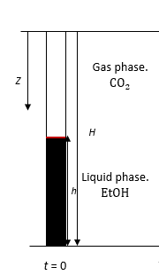
I am trying to simulate the pressurization of ethanol and co2 in a closed vessel. The vessel initially contains liquid ethanol at the bottom and gaseous co2 at the top, separated by an interface. During pressurization, liquid ethanol evaporates from the liquid phase into the gas phase and there is the dissolution of gaseous co2 into liquid co2. Ethanol and co2 are miscible. The fluid flow is assumed to be laminar. The system is isothermal. The fluid properties depend on the composition of the species. Density, viscosity, mass diffusivity changes with mass fraction.
Modeling Approach.
For now, I am not modeling the entire pressurization process. And I am only considering mass transfer due to dissolution of vapor co2 to liquid co2. I am just modeling a steady-state problem, where my initial conditions are pure liquid ethanol & gas co2. At initial pressure of 6Mpa.
Transient model, Pressure based solver. Gravity turned off.
Eulerian multiphase model (Explicit) because the flow is miscible.
Primary phase: liquid , secondary phase: vapor, surface tension = zero.
Mass transfer. The mass transfer is driven by the concentration gradient. For now, I used the species mass transfer option.
Model options: Equilibrium ratio. Equilibrium ratio, constant: 0.4.
Interphase mass transfer coefficient, overall, 3.3e-7.
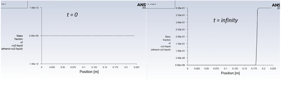
Result.
On the LHS mass fraction of co2 liquid is zero before starting the simulation at t=0. RHS, mass fraction of liquid co2 after running the transient simulation and allowing it to reach a steady state solution. The result make sense. Yes, at steady state the mass fraction show be 0.4 based on how i set it up.
March 1, 2022 at 8:58 amDrAmine
Ansys EmployeeThe eqn 18-578has the correct unit of kg/m┬│(density)*m/s(mass transfer coefficient)*1/m(area concentration)=kg/m┬│s.
March 1, 2022 at 5:56 pmSubscriberThank you,.
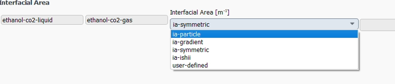
I now understand why I was not getting same result as fluent from my hand calculation. On the interfacial Area panel I chose ia-particle for the simulation, but I was using the formula for ia-gradient in the manual - which is NV_MAG(C_VOF_G(c,ppt)) - for my hand calculation. I think that's the reason my result were off because both formulation give different values.
 I have some follow-up questions.
Consider the image below as my domain. gas phase @ the top & liquid phase @ bottom. Segregated flow. The liquid co2 from dissolution & ethanol are miscible.
Which formulation for the interfacial area is most suitable for my problem? I was using ia-particle before, but after reading the manual it seems to me that ia-symmetric is ideal for my case. Please what do you think?
 2)
2)

If i write a UDF for interphase mass transfer based on the above equation, should I write a UDF for interphase area and multiply it to this equation to get volumetric mass transfer rate? Or will fluent automatic do that if for me I chose one of the options for interfacial area concentration. ?
Thank you.
Regards Abolorunking
March 2, 2022 at 10:00 amAnsys Employee1/If the flow morphologies are assumed to be "continuous" either symmetric or gradient or user defined are the way to go.
2/If you want to write an UDF for mass transfer it should return the mass flow per unit volume and not the mass flux (per unit area). So your UDF should return the mass flux * Interfacial area as single expression. The choice of interfacial area you do in Fluent won't be used if you want to use your own mass transfer rate UDF (but you can access the interfacial area calculated by Fluent if you want to use it).
March 2, 2022 at 10:08 amSubscriberThank you for your response. I will do that and let you know how it goes.
April 3, 2022 at 7:59 amRathore
SubscriberHi DrAmine,
1/Could you please give some example where the interfacial area calculated by Fluent is accessed? I have written the UDF for the mass flux and to make it a mass source in the continuity equation I need to multiply that with the interfacial area per unit cell volume.
2/We access the flow variables like temperature calculated in Fluent as C_T(cell, thread). Similarly, can I directly access the gradient of volume fraction in my UDF using its macro, such as C_VOF_G(cell, thread)?
Thanks in advance, and I appreciate your help.
RegardsApril 3, 2022 at 11:21 amSubscriber
Pending response from .
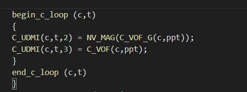
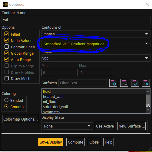
You can access the interfacial area per unit volume using C_VOF_G(c,t) as you rightly said. Be careful as C_VOF_G(cell, thread) returns a vector. So use NV_MAG to convert it to scalar.
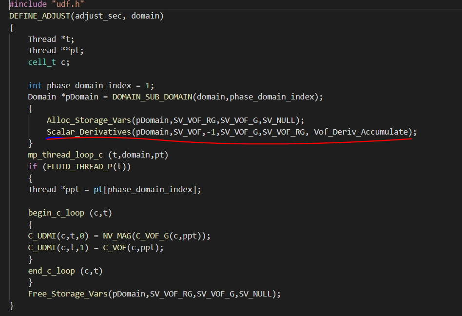
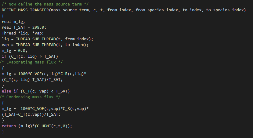
Here is a snippet of my code. I stored the gradient in a UDMI and i defined it in adjust function.
 Let me know if it helps.
Regards
April 4, 2022 at 5:26 amSubscriberthanks for your kind gesture. Let me check this in my code, then I will reply with the outcomes.
Edit: Could you pls provide me few more pre/post lines of this code, actually I am not able to connect it in my code.
April 4, 2022 at 11:26 amAnsys EmployeeYes interfacial area can have different formulations and the one mentioned here is widely used assuming laminar interfacial area. If you want to access the gradients you need either to follow the official way mentioned in the documentation or to follow the non-official way which is pretty simple to find on this forum.
April 5, 2022 at 2:07 pmSubscriberHi, Thanks for your advice, I am able to calculate the gradient of volume fraction at each cell. The UDF is attached herewith:
/*Written and Compiled by Surendra Singh Rathore*/
/* code to calculate the interfacial area density which is also equal to
the magnitude of gradient of the volume fraction */
# include "udf.h"
# define domain_ID 3 /*ID=3 is for vapour*/
DEFINE_ADJUST(adjust_gradient, domain)
{
Thread *t;
cell_t c;
face_t f;
domain = Get_Domain(domain_ID);
/* Fill UDS with the variable. */
thread_loop_c (t,domain)
{
begin_c_loop (c,t)
{
C_UDSI(c,t,0) = C_VOF(c,t);
}
end_c_loop (c,t)
}
thread_loop_f (t,domain)
{
if (THREAD_STORAGE(t,SV_UDS_I(0))!=NULL)
begin_f_loop (f,t)
{
F_UDSI(f,t,0) = F_VOF(f,t);
}
end_f_loop (f,t)
}
}
DEFINE_ON_DEMAND(store_gradient)
{ Domain *domain;
cell_t c;
Thread *t;
domain=Get_Domain(1); /*ID=1 is for mixture*/
/* Fill the UDM with magnitude of gradient. */
thread_loop_c (t,domain)
{
begin_c_loop (c,t)
{
C_UDMI(c,t,0) = NV_MAG(C_UDSI_G(c,t,0));
}
end_c_loop (c,t)
}
}
April 5, 2022 at 2:13 pmSubscriberMy another doubt in that same series of question is, how do we store or display the UDM at each iteration? Here in FLUENT it needs to be updated using "EXECUTE ON DEMAND" and then it gets frozen until new "EXECUTE ON DEMAND" is re-entered.
April 5, 2022 at 2:23 pmSubscriberHi
Go to: User defined- Memory (if u use 2 UDMI select 2) - Scalars (Select the number of scalars u used).
Sorry for late response. I used a different code for the VOF gradient. Yours is fine too.
 Always suggestion is the best on this matter. So, I'd wait for his comments if I were you.
April 5, 2022 at 3:32 pmSubscriberthanks for the suggestion.
Since in the newer version (21R2), the gradient of Volume fraction is calculated directly in the Solver. Therefore, instead of creating UDS and UDMs, can we directly not access its value using some kinda Macros?
April 5, 2022 at 5:33 pmAnsys EmployeeI did not look thoroughly into the UDFs but both methods are okay. The official method provides you directly with the gradient of VOF. Moreover in newer version with VOF model one can access the interfacial area.
April 5, 2022 at 5:33 pmAnsys EmployeeOfficial method is documented in the Customization manual
April 5, 2022 at 5:35 pmAnsys EmployeeJust think about parallelization when writing UDFS
April 6, 2022 at 7:19 amSubscriberDear your help is appreciated.
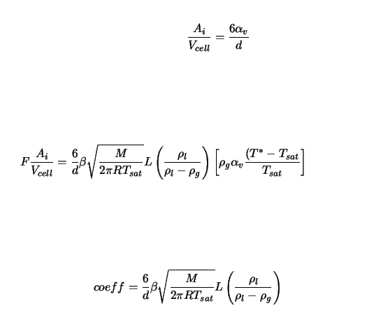
I have just one question to conclude the discussion, which formula of interfacial area density the FLUENT uses in the VOF based Lee's model of evaporation/condensation? I believe the mass source term (kg/(m^3).sec) in the continuity equation is created using mass flux (kg/(m^2).sec) and the interfacial area per unit cell volume (m^-1). In the FLUENT user manual, it is given only for the Mixture and Eulerian models and that is simply 6*phase volume/diameter, which is not true for the VOF model.
April 6, 2022 at 11:11 amSubscriber
I believe you are accessing your interfacial area concentration (C_VOF_G) using fluent macro? If that is case, then I wouldn't worry about the formula for computing the IAC in the VOF method. Just multiply the VOF gradient magnitude obtained from (C_VOF_G) to your Schrage equation and you should be in good shape. You should be worry about the formula if you wanna write your own UDF for the IAC, it doesn't seem to be the case here.
If you have to write a UDF for your case (which I am assuming is a free surface flow), then see 's comment : "If the flow morphologies are assumed to be "continuous" either symmetric or gradient or user defined are the way to go" Check the user manual for the formula used for symmetric or ia-gradient formulation.
I hope it helps.
April 22, 2022 at 6:18 amSubscriber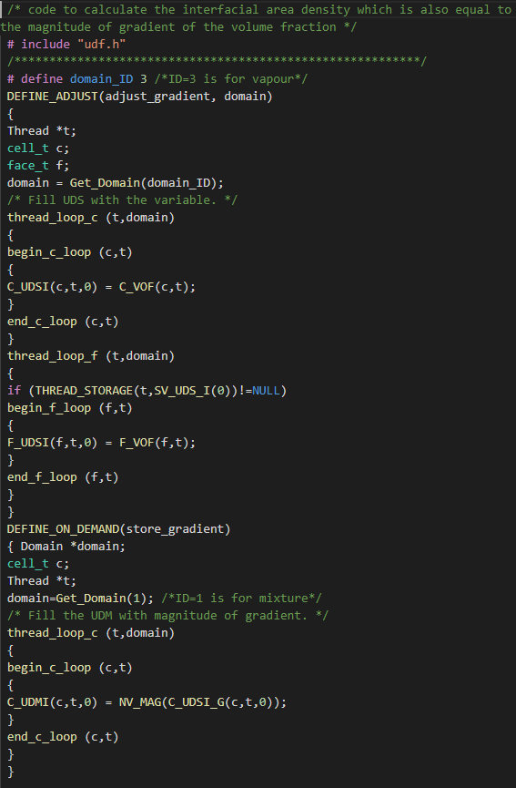 Dear Instead of writing this long code to calculate and store the gradient of volume fraction, can I directly use its macro **NV_MAG(C_VOF_G(c, t))**?? Since this long code needs to perform execute on demand which I wonder doesn't continue throughout the iteration!!
April 22, 2022 at 6:24 amSubscriberI am now left with two choices, either using the macro of volume fraction gradient directly , or storing the volume fraction gradient as a UDS and storing further it to UDM and using it in my code to calculate mass source. The second choice which now I am trying although running fine but needs to execute on demand to transfer the UDS to UDM...multiple times during calculations. Please rectify this issue.
This is the second part of the code, please consider in continuation with trailing comment of mine...
Viewing 19 reply threads- The topic ‘How species interphase mass transfer is implemented in fluent. Hand calculation not matching fluent’ is closed to new replies.
Innovation Space Trending discussions
 Top Contributors
-
peteroznewman
 6379
6379 -
scabo
 1906
1906 -
Dennis Chen
 1457
1457 -
javat33489
 1308
1308 -
Shyam Prasad V Atri
1022
Top Rated Tags
© 2026 Copyright ANSYS, Inc. All rights reserved.
Ansys does not support the usage of unauthorized Ansys software. Please visit www.ansys.com to obtain an official distribution.
-
Ansys Assistant will be unavailable on the Learning Forum starting January 30. An upgraded version is coming soon. We apologize for any inconvenience and appreciate your patience. Stay tuned for updates.