-
-
February 18, 2022 at 3:21 am
sandeep_chamoli
SubscriberHi Team,
I am want to do the magnetooptical material simulation. I have a tensor of magnetooptical material from literature. I have few questions.
(1) the value we need to keep here in FDTD material data base is the eigen value of this tensor?
February 18, 2022 at 11:30 pmGuilin Sun
Ansys EmployeeI guess you have read this article: https://support.lumerical.com/hc/en-us/articles/360034394694-Creating-anisotropic-optical-materials-in-FDTD-and-MODE
A1: the values here are from the diagonalized elements: exx,eyy, ezz
A2: U is the conjugate transpose of the eigen vector V. If it is real matrix, then it is just a transpose.
Only when you know the material diagonal tensor can you use the rotation transformation. Permittivity rotation grid attribute
A3: propagation direction does not define the tensor, it is the tensor that defines the material anisotropy. Therefore, you may need to know what anisotropy of the material you desire to have light propagating along z. Please find more information about anisotropy and light polarization from some books.
February 21, 2022 at 1:56 amsandeep_chamoli
SubscriberHI , Thanks.
I am able to see the rotation in the polarisation, this part is fine.
But i have a question.
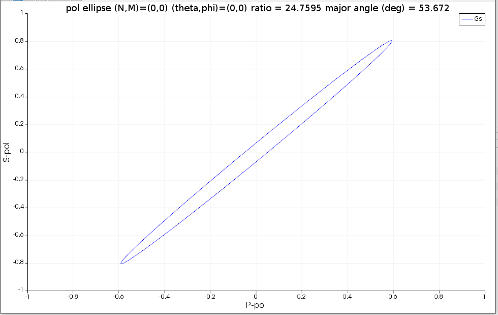
first, i am going +z direction , and i have certain pol rotation in light after passing through the magnetooptical material. I can calculate that pol state using pol ellipse, as given here. https://support.lumerical.com/hc/en-us/articles/360034395234-Calculating-the-far-field-polarization-ellipse
Now, when i am going back (-z), why the polarisation is going back to its original state , i think it should further add polarisation ?
February 22, 2022 at 4:27 pmGuilin Sun
Ansys EmployeeNot sure what do you mean "the original state". Is it the same as the +z polarization state, or the incident state? The device is not special to separate forward and backward propagation. Please first test online example. As long as everything setting is the same as +z case, except the propagation direction, I do not see any physics that prevent to have the same result, except it is the kind of circulator. Please carefully check the settings and think over the physics.
February 23, 2022 at 12:44 amsandeep_chamoli
SubscriberHi, Noted.
Can you please tell me , how to get the information of apmplitude of S and P light from the following figure. Because once we know the S and P amplitudfe and their phase difference (which is available in pol. ellipse analysis group result) we can get the same pol. state shown in this figure.

Using the definition from equation 10 here , https://www.waves.utoronto.ca/prof/svhum/ece422/notes/03-polarization.pdf . Its giving back same major angle but ratio is not same.
February 23, 2022 at 7:22 pmGuilin Sun
Ansys EmployeeYou can either using that analysis group to get Gp, Gs, or using grating analysis with your own script to get the farfield vectorial fields of Gp and Gs. Please refer this script
https://support.lumerical.com/hc/en-us/articles/360034407034-gratingpolar-Script-command
To count for all the grating orders this script gives results in spherical coordinate. you will need to extract the fields at the specific theta,phi to get the complex valued of Ep and Es. Please note that this is different to plot ellipse polarization. I would suggest you to read the scripts in the analysis group, get to know how does it work to get the ellipse and how to get the Ep and Es at the diffraction angle (diffraction order) .
Viewing 5 reply threads- The topic ‘Magnetooptical materials , Polarisation Rotation’ is closed to new replies.
Innovation SpaceTrending discussionsTop Contributors-
4597
-
1495
-
1386
-
1209
-
1021
Top Rated Tags© 2025 Copyright ANSYS, Inc. All rights reserved.
Ansys does not support the usage of unauthorized Ansys software. Please visit www.ansys.com to obtain an official distribution.
-
The Ansys Learning Forum is a public forum. You are prohibited from providing (i) information that is confidential to You, your employer, or any third party, (ii) Personal Data or individually identifiable health information, (iii) any information that is U.S. Government Classified, Controlled Unclassified Information, International Traffic in Arms Regulators (ITAR) or Export Administration Regulators (EAR) controlled or otherwise have been determined by the United States Government or by a foreign government to require protection against unauthorized disclosure for reasons of national security, or (iv) topics or information restricted by the People's Republic of China data protection and privacy laws.


