TAGGED: beams-and-shells, coupling, meshing, structural
-
-
February 17, 2022 at 5:21 pm
Cameron Crook
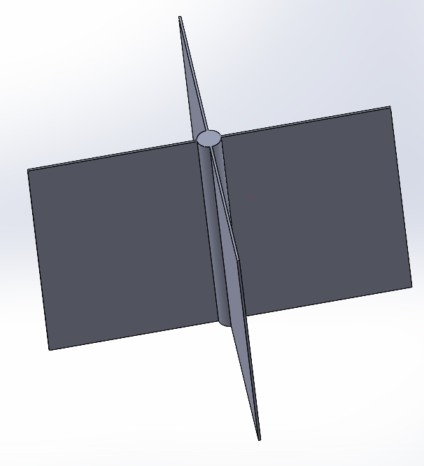
SubscriberI have a geometry of thin beams and plates connected along the plate edges. My goal is to use shell (shell281) and beam (beam189) elements to model the geometry. However, the overlap of the beams and shells without any regard for the diameter of the beam leads to erroneous results. A simplified base example is shown below where the beam is exaggerated for clarity. The beam is too thin to reasonably mesh it as a solid. Therefore, I wanted to know if there were a way to couple the edge of a shell element to the surface of a beam element. Is this possible with some sort of bonded contact? My intended geometry is more complicated than below so ideally I'd like to avoid manually coupling nodes myself since the beam orientations is complex.
February 17, 2022 at 5:27 pmpeteroznewman
SubscriberWhat is the diameter of the beam and the thickness of the shell. If they are the same material and the dimensions are not so different, do you even need to model the beam?
February 18, 2022 at 5:23 amCameron Crook
SubscriberThe diameter and thickness are sufficiently different that they needed to be modeled separately.
February 18, 2022 at 11:02 pmpeteroznewman
SubscriberTry using SpaceClaim. Create beam elements from lines and create surface bodies that intersect at the line. On the Workbench tab, click the Share button.
When you open this in Mechanical and mesh it, the beam elements and the shell elements will share common nodes at the intersection.
February 20, 2022 at 8:43 pmCameron Crook
SubscriberApologies, I should have specified I am using Ansys Mechanical APDL. For other reasons, I won't discuss here, I am not using spaceclaim.
Viewing 4 reply threads- The topic ‘How can I mesh/couple edge of a shell element to a beam element surface?’ is closed to new replies.
Innovation SpaceTrending discussionsTop Contributors-
5094
-
1831
-
1387
-
1248
-
1021
Top Rated Tags© 2026 Copyright ANSYS, Inc. All rights reserved.
Ansys does not support the usage of unauthorized Ansys software. Please visit www.ansys.com to obtain an official distribution.
-


